

The Equipotential Surfaces of a Dipole
BlackBoard Notes
- Notes for Jeff:
- Draw 4th section first, then the 3rd, to make sure there's enough room for large pics!
- These are essentially the same notes used for the 152 experiment (just remove the reference to the Lab Practical, and change "Potential Field" to "Equipotential Surfaces"), which hopefully was performed the previous week. If possible, the 104 group will meet in the 152 lab so these notes won't have to be rewritten.
======================= Photo - Click for a Larger Version =============================

Spring 2027: Need New Photo
======================= First Board Section =============================
- Map the equipotential surfaces around a pair of "charges"
- Draw a few E vectors
- "Step #0": Learning to use a Multimeter as a Voltmeter
- Read through "Using a Digital Multimeter"
- Follow exercise on pg. 4
- Record results on designated sheet in your journal
======================= Second Board Section =============================
- Conducting paper configuration:
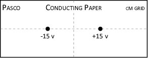
- Set voltmeter precision to measure voltage to 1/10th of one volt D.C. (Direct Current)
- (point out that this means one digit after the decimal!)
- Always record all meter settings in your journal
- Turn voltmeter OFF when finished!
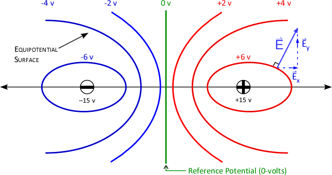
======================= Third Board Section - Leave Room for Two Big Pics! =============================
- The "ideal" equipotential surfaces around two charges:
- Note for Jeff: Draw Horizontal axis in middle of board; use green color for 0-V reference potential line to match the green connector
======================= Fourth Board Section =============================
- Topographic sketch of equipotential surfaces:
- Note for Jeff: Use green color for 0-V reference potential line

Return to Setup
| Revised:
15 Jul 26
|
Canton, NY 13617
|