- Computers are needed for lab this week
- I set all meters to a "neutral" setting (I use hFE) before each lab section. That way students don't start lab with a meter already in the correct setting
- In the pre-lab, I walk everyone through connecting wires to the meters and connecting the resistor to the power supply (without meters). I spend time going over the connection of the voltmeter and ammeter, and talk about connecting the circuit to the power supply.
- Each setup has five wires – that's all they'll need for this experiment!
- Tell students that if they think they need more wires, they're doing something wrong and they need to talk with you!
- Discuss which ports on the meter to plug wires into (and to Never use the '20A' terminal!)
- Start with two wires in voltmeter: red in V terminal, black in Com
- Then plug one (short) wire in the ammeter: place in A terminal, which reminds students that they must open the circuit to insert the ammeter in series
- Common mistake: they will put the free wire from the circuit in the V terminal; it must go in Com
- Power supply:
- red wire in red + terminal, black wire in – terminal. Don't use the terminal labeled GND; the circuit won't work!
- Keep Current knob so that white mark is vertical. Don't change the current limiter setting, or the circuit may not work if the current is turned down
- Make sure Voltage knob is turned all the way off (counter-clockwise) before turning on power switch for the first time
- Two multimeters are used this week, as an ammeter and voltmeter. A sticky note labeled A or V has been arbitrarily placed on each to help students figure out what they're connecting and reading
- (Spring 2026) Fun Fact: One lab group worked with the lights off (student with a migraine). If the LED is oriented correctly, it will glow red when measuring resistance. It's most bright in the continuity setting. Reversing the LED does not cause it to glow.
 We no longer use the box containing a resistor and LED diode, so the following is kept for historical interest We no longer use the box containing a resistor and LED diode, so the following is kept for historical interest- A box with a resistor and LED are provided for measurements, the idea being that they simply connect the wires to the appropriately labeled ports and take their measurements. In practice, they have a difficult time following instructions, and I'm not sure they really know what they're measuring.
- Two resistors are in the box: the larger (physically) resistor is the one that they're measuring; the smaller (physically) resistor is in place to protect the LED from incorrect connection that will short it out - and someone always connects the circuit incorrectly
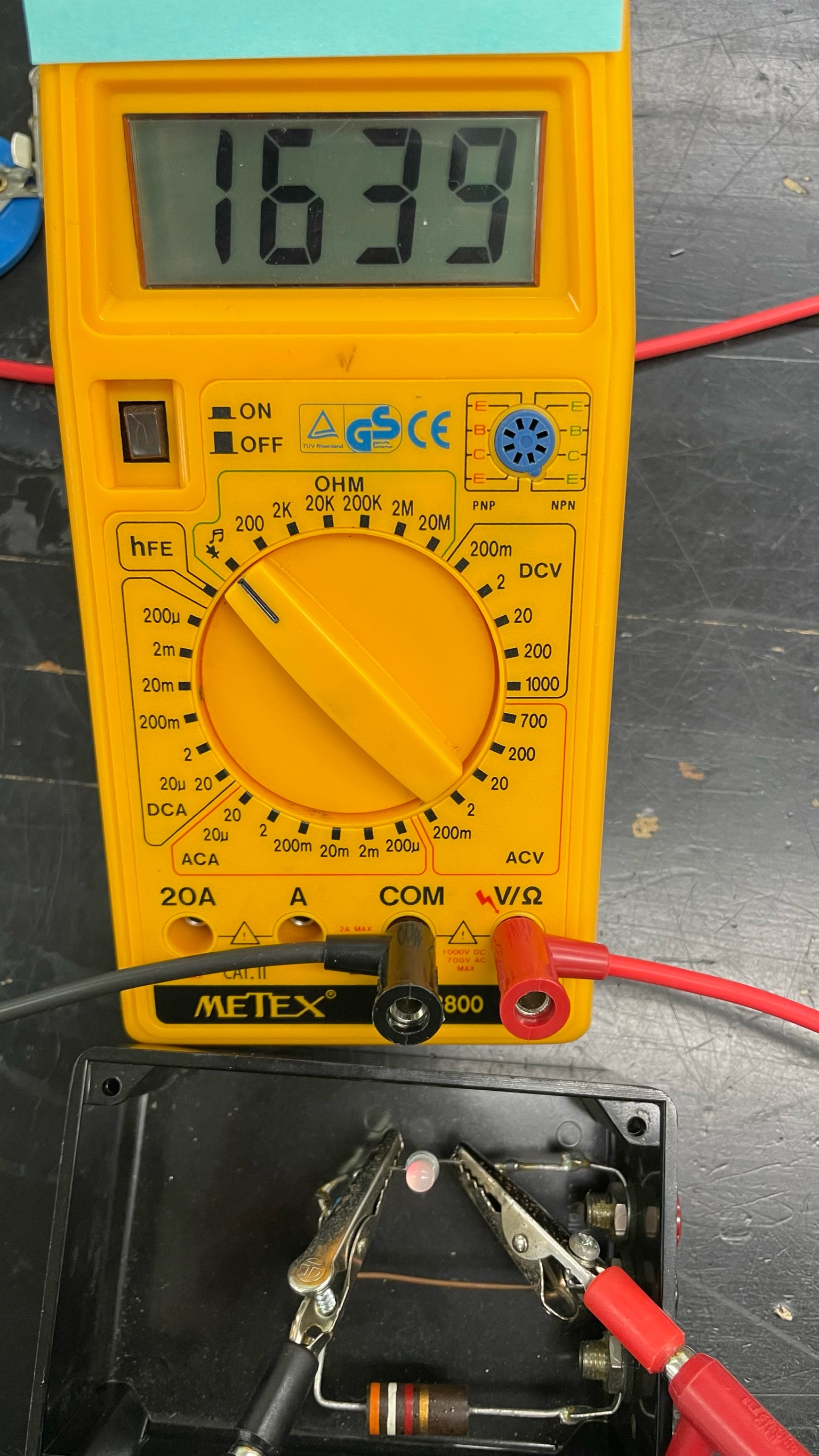
- When attempting to measure the resistance of the LED, students should get the overload warning (1 on the left side of the display). However, if they set the multimeter to the 'Continuity/Diode' position, they will see a measurement and record that as the LED's resistance. Unfortunately, this is not a measurement of resistance. The multimeter sends 1 mA of current through the diode, and the display registers the voltage drop across the diode, in millivolts. Note that the LED is illuminated red in the photo at right from the current supplied by the multimeter. If we used a standard LED, switching the leads should give the overload warning; the LED we use is bi-directional, so switching the leads will also result in a measurement and the LED will glow green. In the future, I'll add a warning about this to the instructions, but since nobody reads the directions, it will all be for naught.
- Students print three graphs, one for each circuit element. The range of I and V used for each makes it impossible to combine the graphs
- Note: this question has been removed, since students couldn't figure out what it was asking. I've left this here in case we reinstate the question.
- The final discussion question asks students to connect their resistance measurements with the ohmmeter to their graph for the non-ohmic circuit elements
- Their measured resistance for the light bulb is very low; that's because it's measured at a very low voltage (supplied by the multimeter). As the voltage increases, the slope decreases, so the resistance increases {since R = (slope)-1}
- The measured resistance of the LED shows an open circuit ('1' appears on the left side of the ohmmeter display). The graph of the LED is initially flat (slope = 0), and therefore the resistance is infinite. After the voltage has reached some non-zero threshold value, the LED lights and the voltage increases at what appears to be a nearly linear rate
|