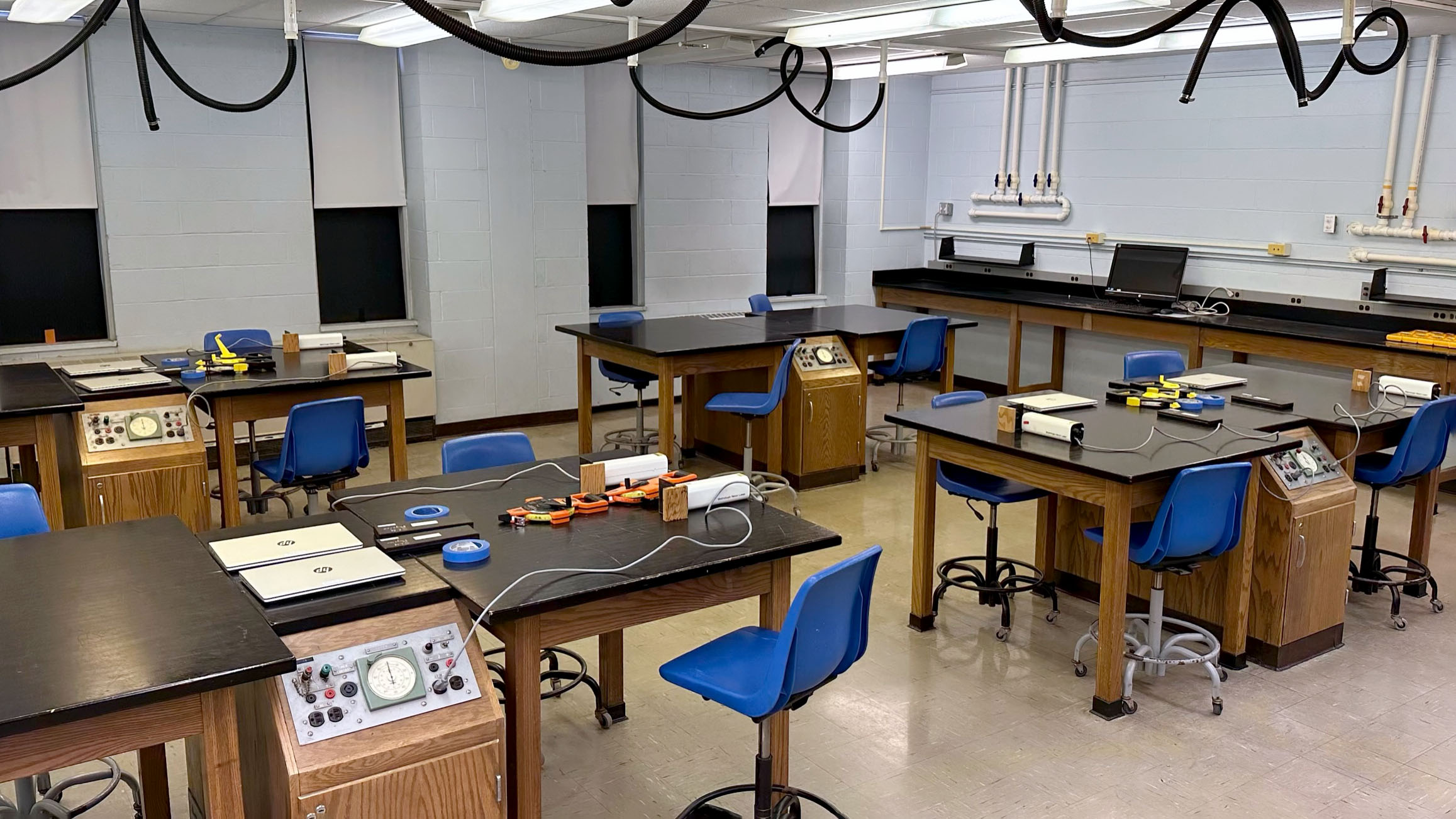
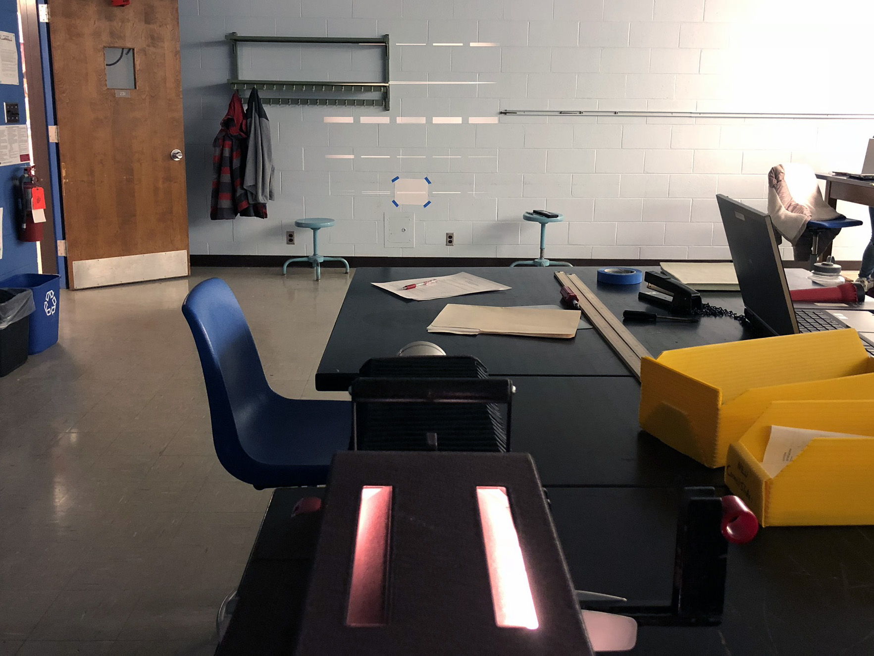
Room setup.
Four lasers are pointed at the left wall and
two lasers are pointed at the rear wall |
Four red lasers on left side of room, aimed at
left hand wall |
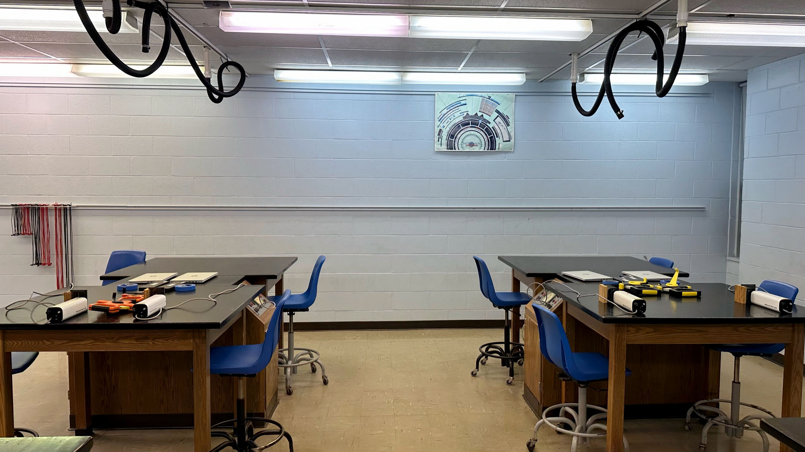
Four lasers are pointed at the left wall |
Two lasers are pointed at the rear wall |
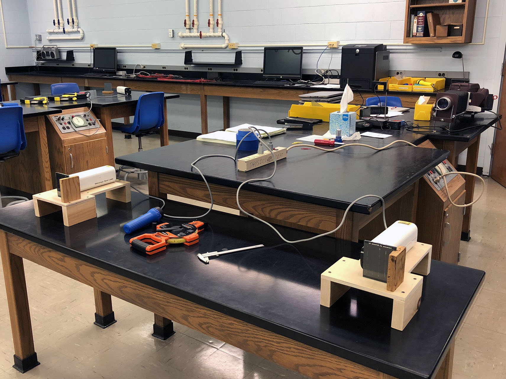
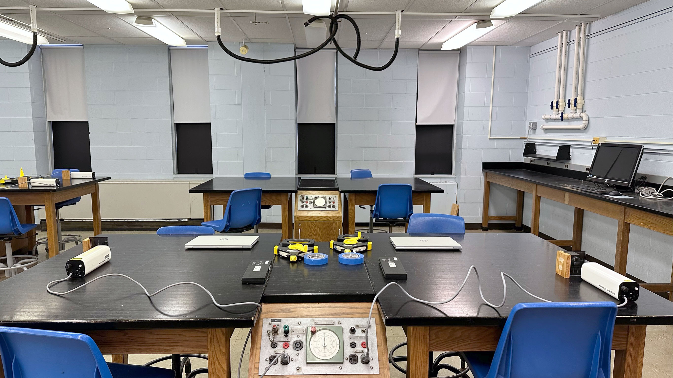
Move the long table near the instructors bench to hold a 7th and 8th laser.
Note: Move table here, even if those lasers aren't needed |
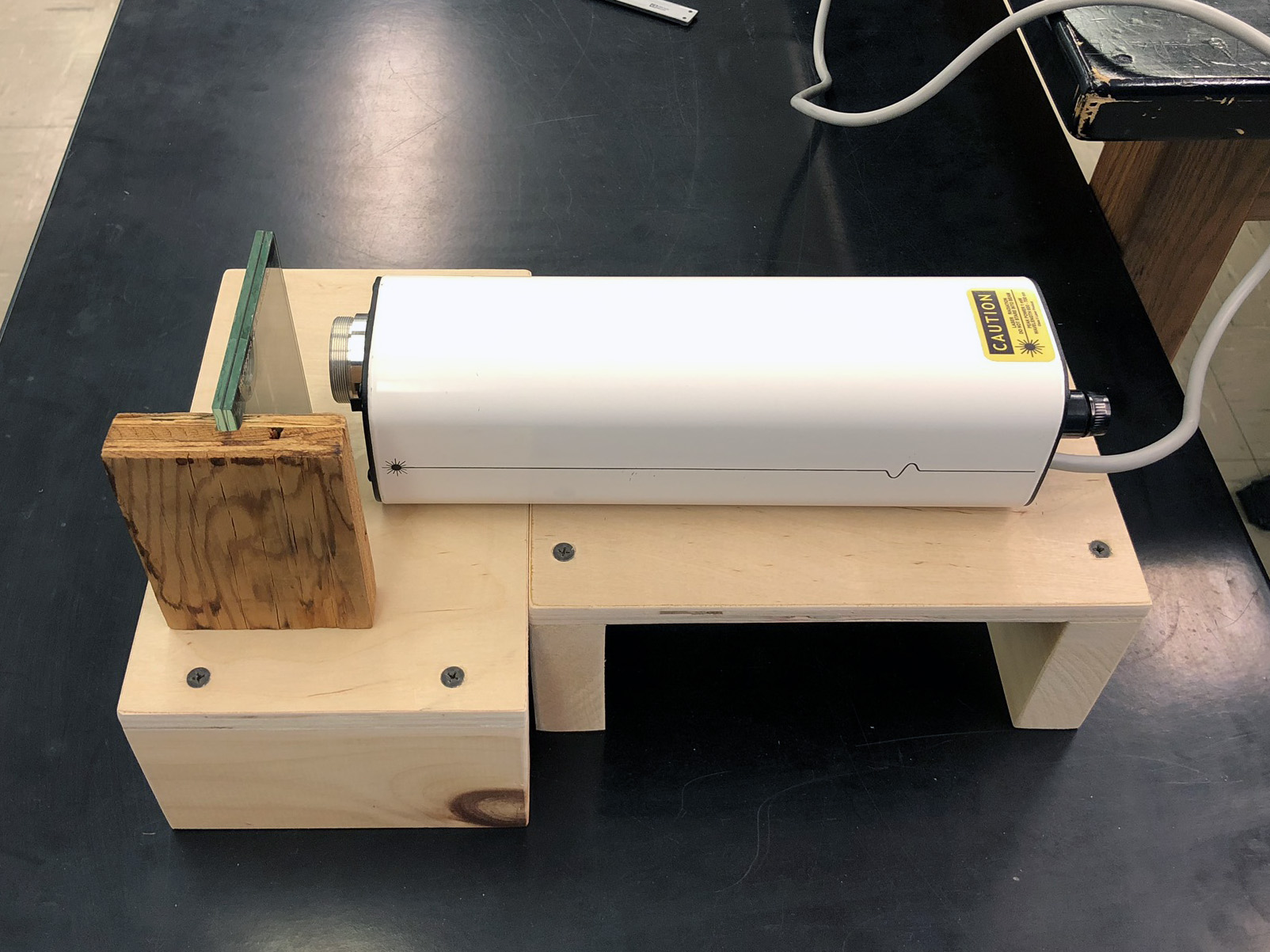
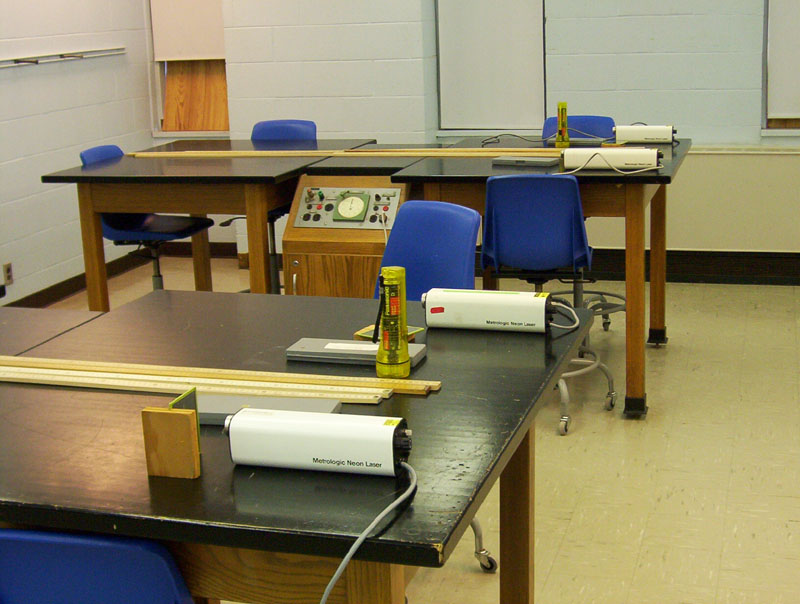
Use two tall wood platforms to elevate each laser above the grout line on the wall.
Note that the platforms are positioned 90° to each other |
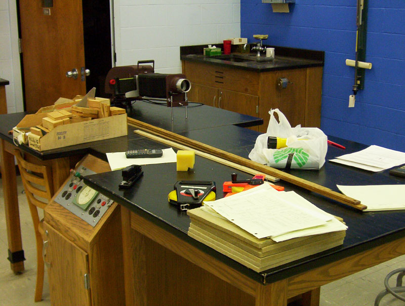
The Cornell slide projector (a "Delineascope"!)
is placed on the front bench, and aimed at
the left side wall |
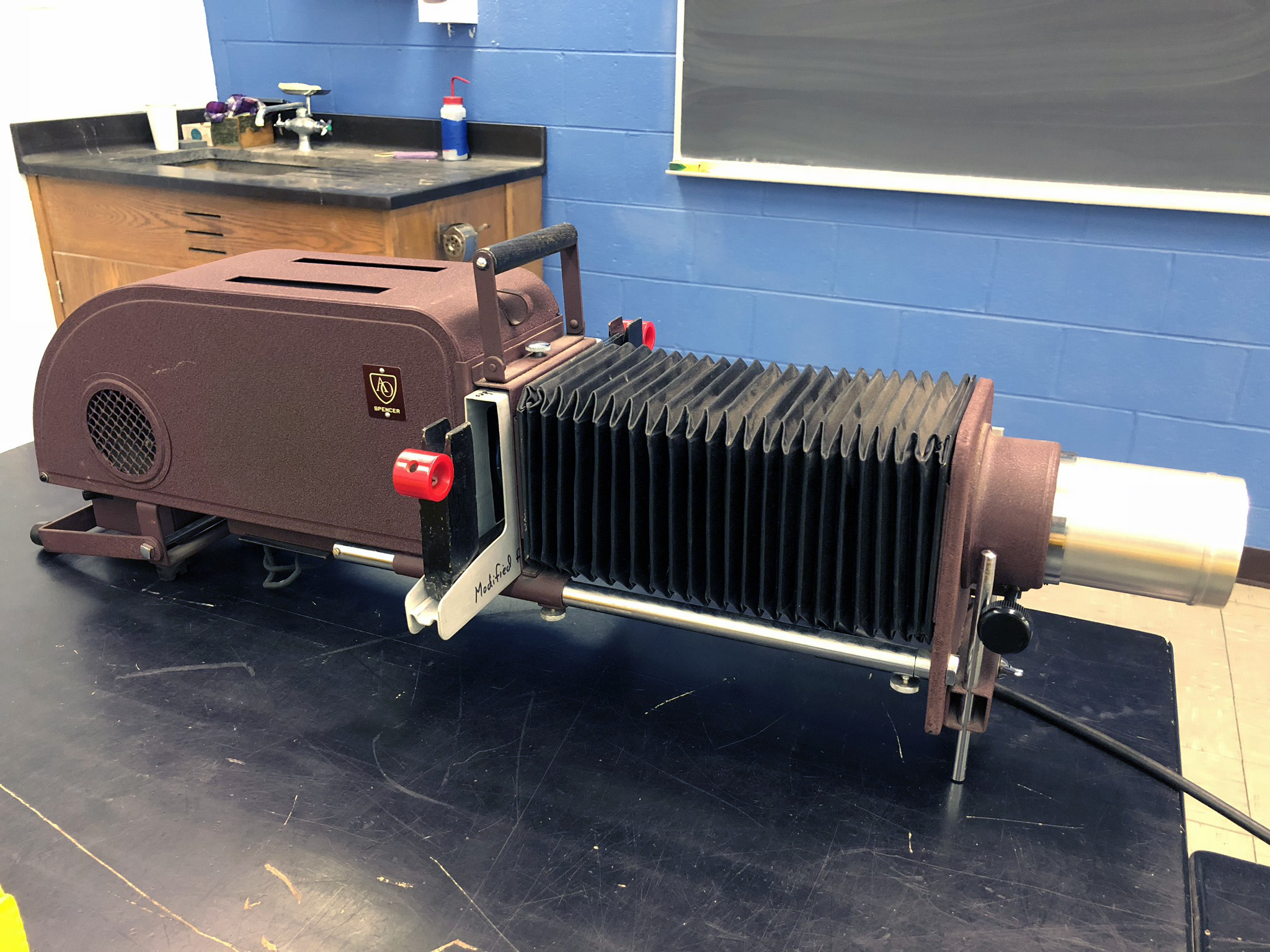
Delineascope.
Note that the one slide holder has been
modified
to accommodate thicker slides! |
Aim projector at left side wall, to the right
of the coat hangers.
Note the sheet of paper taped to the wall |
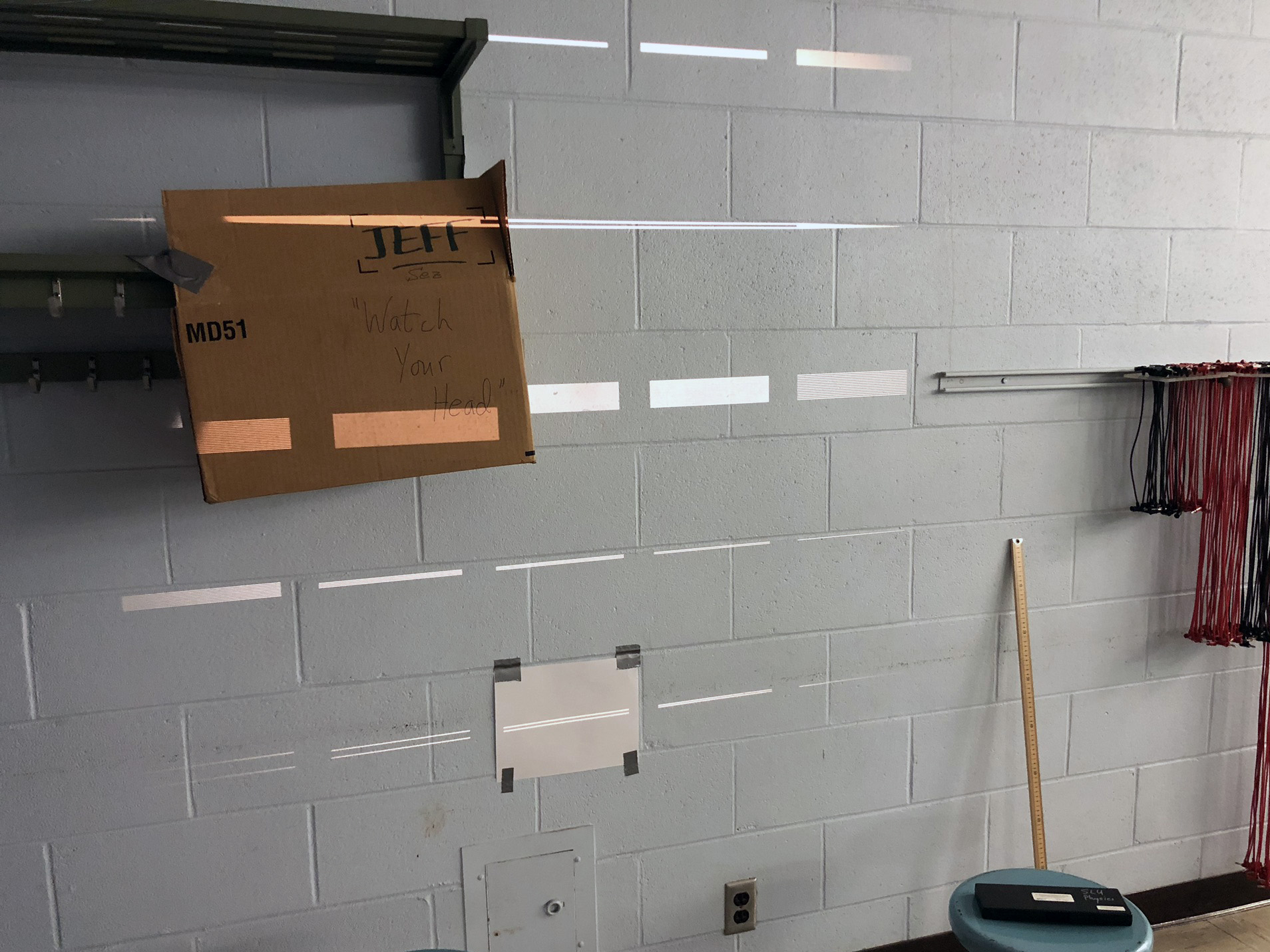
Slide apertures projected on the wall. A sheet of paper is taped
to the wall over the slits that students will measure.
Note the box taped to coat rack to prevent cracked skulls
(Ask Tim Cunningham '21) |
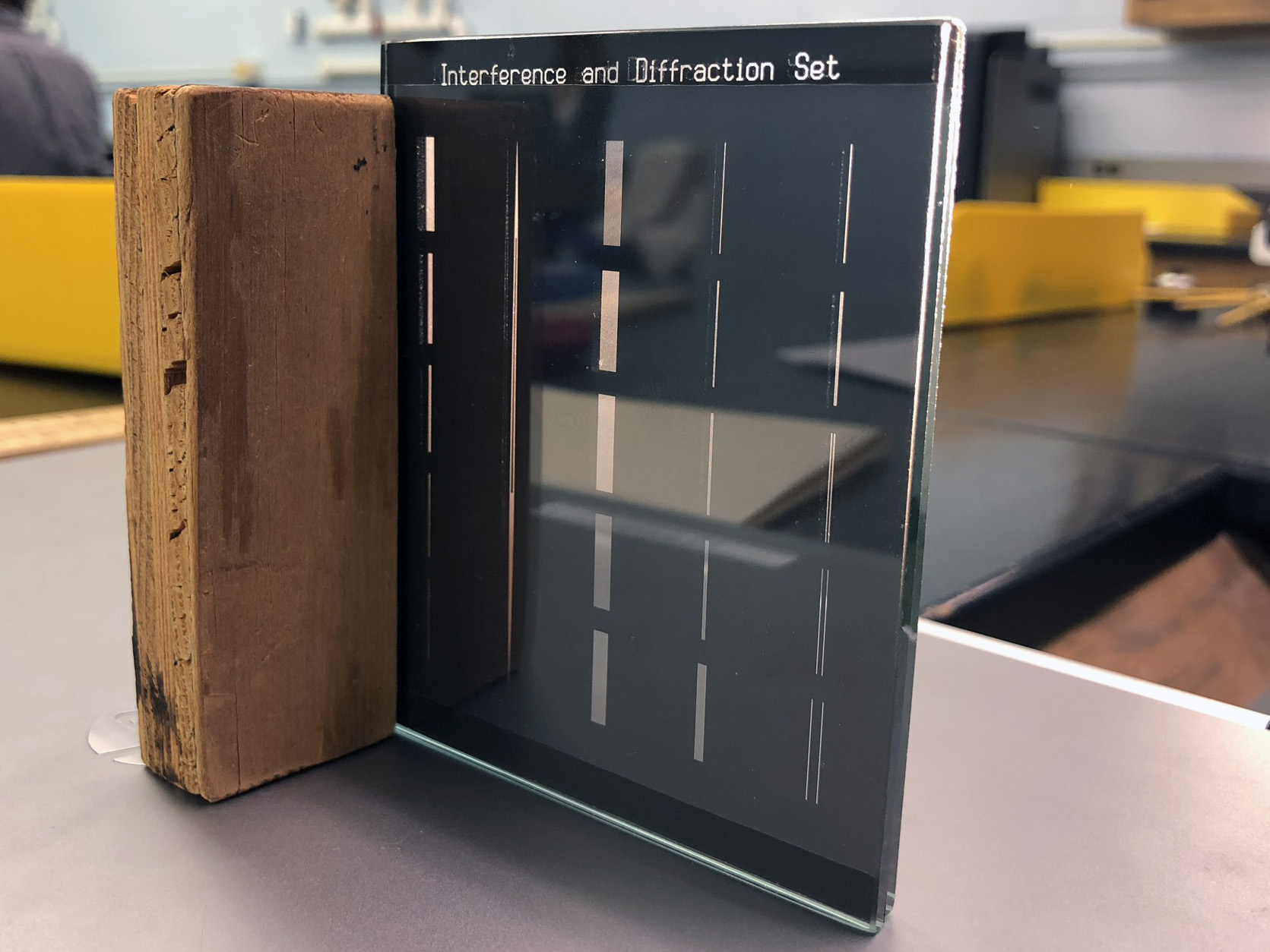
Cornell slide (with label at top) propped up by slide holder on left side |
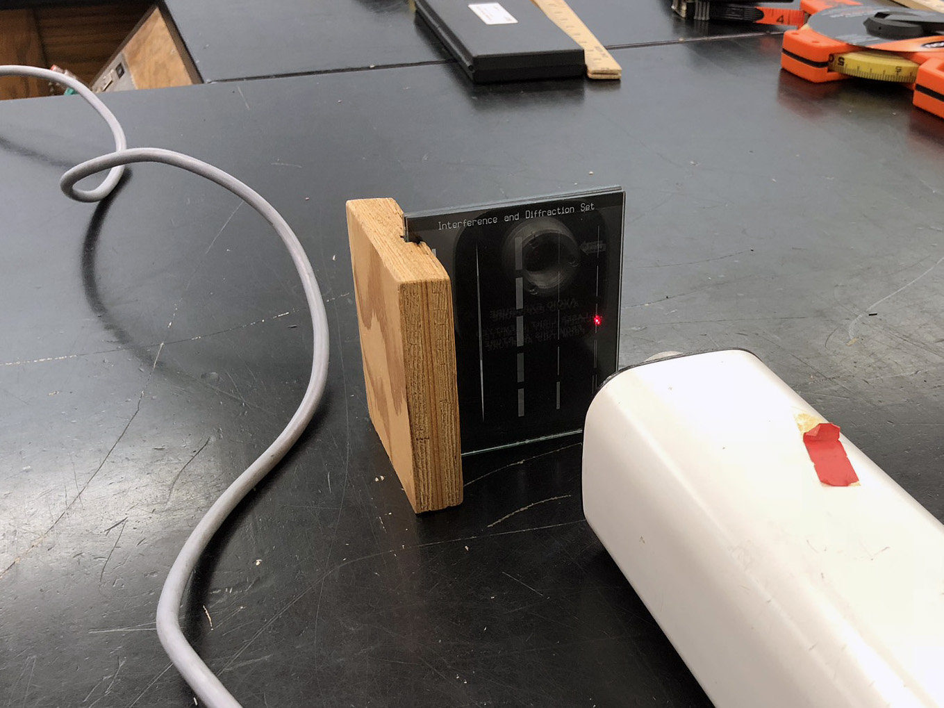
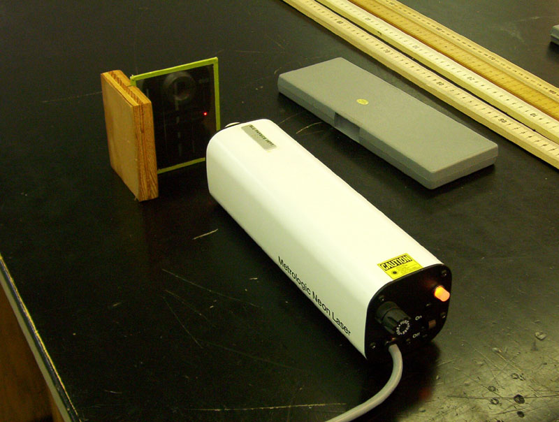
Point the laser at the right-most column and
laser is aimed at desired slits |
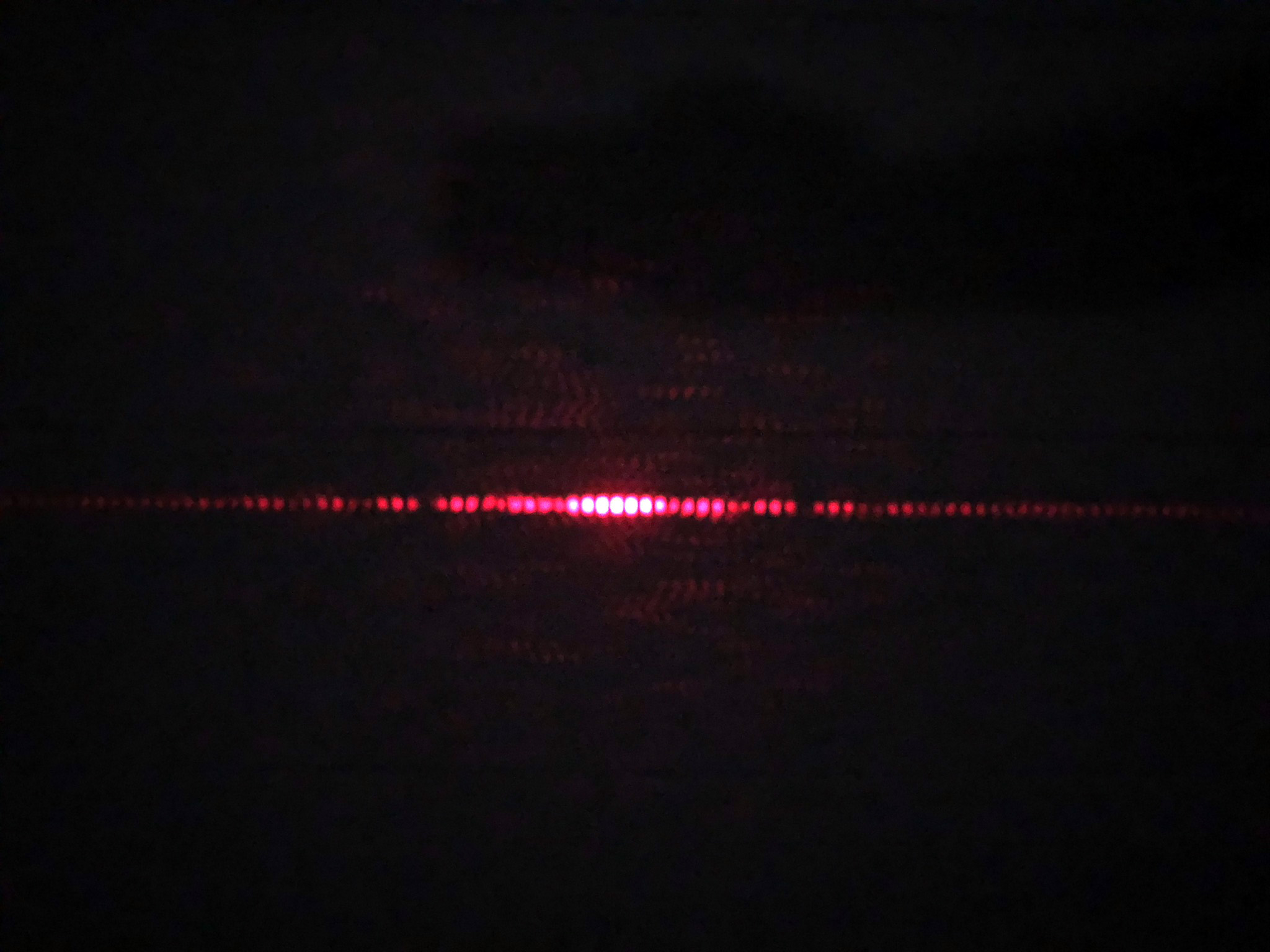
The diffraction & interference pattern students will examine
|