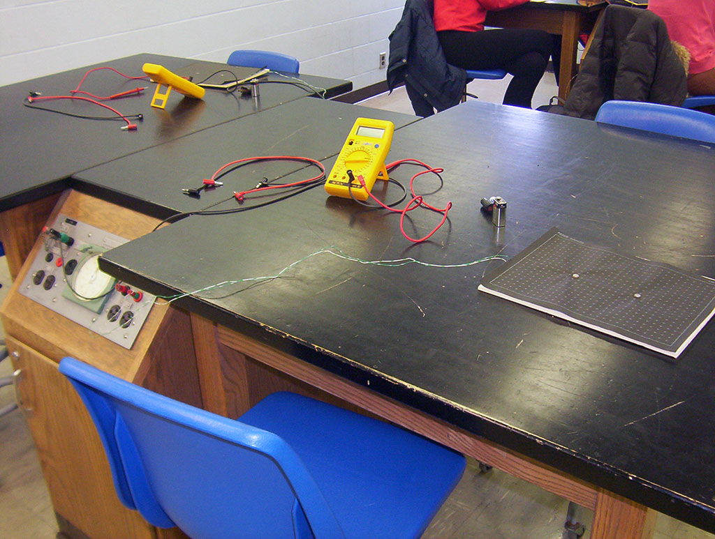
Board setup
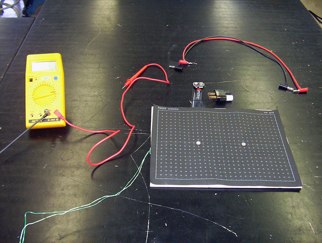
Conducting board, extra wires (red & black),
9v battery, widow maker (no longer used!),
multimeter, and meter probes
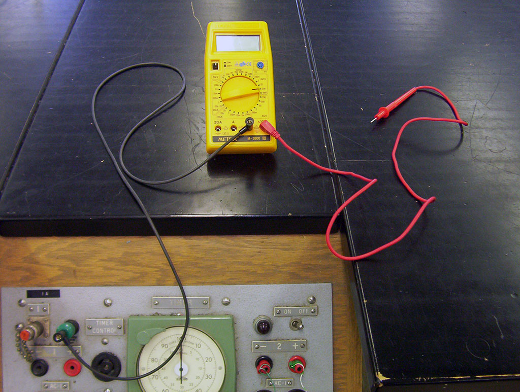
The COM terminal of multimeter is connected
via a long black wire to the green terminal
of the power panel. Left screw of conducting paper is
connected to black (-) terminal,
right screw to the red (+) terminal
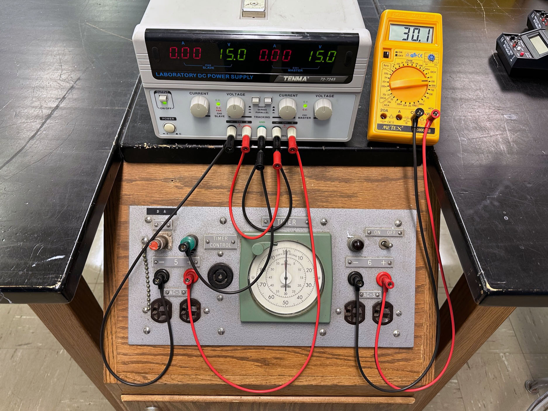
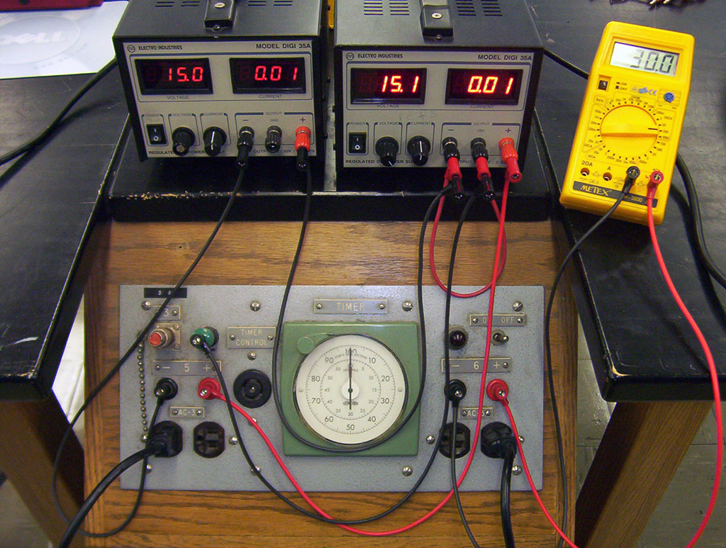
Dual power supply (preferred) on instructor's bench.
See setup instructions for wiring directions
If a dual power supply is not available, place two single power supplies
on instructor's bench. See setup instructions for wiring directions