- Computers are NOT needed for lab this week
- An electronic balance is needed this week
- Measure the radial force for a mass traveling in a circular orbit
- During the pre-lab, I talk them through the FBD and direction of forces for each part of the experiment

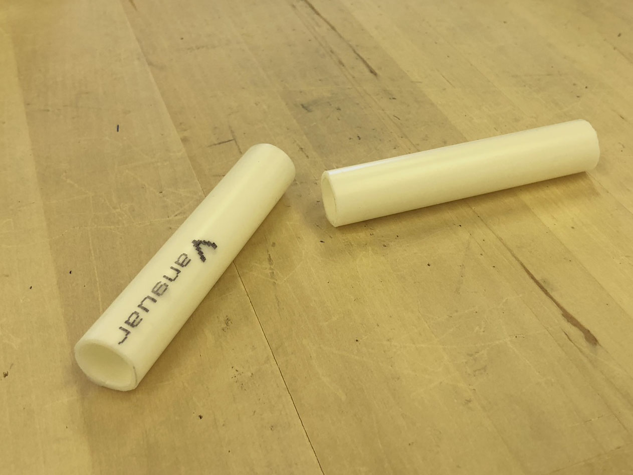
- This is the first time that vernier calipers are used! Each person should have their own pair of calipers. Briefly explain the different measurements that can be taken with the calipers (inside; outside; depth). Each setup has two pieces of plastic pipe (shown at right) that students can use for practice (measure the inside and outside diameters). Tell students to follow the directions carefully (hah!), and check that they have read the vernier scale correctly
- Stuff Jeff will (hopefully!) do before lab:
- Set up a couple of electronic balances
- Check the balance between Bob and counterweight
- Level the base of the apparatus (using the round bubble level)
- Spray WD-40 on the pulley to reduce friction (and hence the load required to put Bob in the correct position). Note that pulley friction might still be a source of error
- The apparatus has been leveled in its current location on the bench. Students should check the round bubble level to make sure it's still level. The apparatus shouldn't be moved on the table, since the tables are not level and changing position on the bench will screw up everything. Also be sure that the bench does not interfere with the string supporting the extra mass, m2 (static part)
- Bob and the counterweight should be balanced: loosen the screw holding the 'yardarm' in place, and make sure that it pivots gently on this point. It's important to make sure this screw is very tight before the apparatus is rotated; if the yardarm slips, the radius will not be the same as what they measured
- Students should keep their linear measurements in units of cm until the force is calculated
- If students will make a mistake, it will be with measuring the radius of the orbit: some never figure out how to read the vernier calipers (for diameter of pointer and rotating shaft), and they frequently read from the wrong side of the caliper jaws on the ½-meter stick, causing an error of 2 cm per caliper. The radius will be 16 to 18 cm; after students tell you their measurement, quickly confirm using a plastic ruler
- I created this map to keep track of the radius measurements for each setup. This is especially handy when grading. I'll try to take measurements (with a plastic ruler) during the equipment setup and will make copies for each lab instructor
- Measured values:
- Dshaft = 1.270 cm; Dpointer = 0.318 cm; mBob ≈ 445 g; T ≈ 0.7 s; F = 5 - 6 N
- If they measure T ≈ 1.5 s, they probably had the photogate in Pend mode so they actually measured 2T (like a group I just had). Fortunately, the data are still salvageable; dividing the period by 2 should give the correct result
- Problems:
- Is the orbit truly circular? Nope. The apparatus tends to wobble slightly as it rotates. Students want to blame the fact that they're turning the shaft by hand, but the difference between their min and max period is usually very small, typically less than 5% (although some suck at this, getting 10% or higher. *sigh*). Be sure to ask students about the assumptions that are made for this experiment (it appears in boldface, italics and double underlined on p. 2 of the instructions!)
- Rarely, someone will ask about the mass of the spring holding Bob, and if it contributes to the uncertainty in the force. The spring mass is 15.7 g, which is 3.5% of Bob's mass; I'm guessing that entire spring mass doesn't count towards the measurement of the spring force, so it likely isn't an issue
|
