- Computers are needed for lab this week
- There are three experiments for students to perform individually. Jeff will make copies of the instructions for each section, and will circle a numerical sequence (in the upper left corner) for students to follow. This gives each student a starting point, minimizing confusion and wait-times for equipment (hopefully). Tell students to follow the sequence, but if all apparatus for a particular experiment are in use, they should skip to something else
- Each of the three experiments has 8 setups, so that minimizes the chance that someone will have to wait for an apparatus to become available. If you have a large section (14 or more), then it's possible there might be a slight backup
- Before the first lab section, I put a box with all of the magnets and resistors in the cabinet under the instructor's bench. I put each of these out on the benches just before lab begins. I put them away every night, in the cabinet below each lab bench, in case a student goes into the lab to practice
- Before each lab, I check the following:
- All power supplies have the voltage knob turned all the way off, the current limiter knob with the white line vertical
- All multimeters are set to the hFE setting (a neutral position)
- All resistors and magnets are placed in their appropriate positions
- Optical bench components are set in their correct positions (details below)
- All computers are plugged in and boot up to the login screen (and are not still logged in from a previous user)
- Practice materials will be placed on the table in the study area of the hallway each day, so that students from other lab sections can practice
- Briefly go over each experiment, pointing out their location in the lab. The third experiment (wavelength of a laser) will have four additional optical benches set up in the Modern Physics lab (Bewkes 202) or in the Astronomy lab (Bewkes 232), or in the College Physics lab (Bewkes 204). Be nice to Jeff and he'll tell you where things are set up for the day
- Tell students to let you know immediately if they think they have an equipment problem; they should also watch the multimeters for the 'low battery' warning.
- Note: The following was a big problem in the past; not so much anymore: Students should make sure they have connected to the network when using a laptop before starting the graphing: they should open "Computer" and make sure they see network drives (P: and T:). If no network drives appear, have them log out and in again (restart isn't necessary)
- Students can't use notes, but it seems that none of them ever look anything up on the computers. I wouldn't do anything if I saw someone pull up the instructions for KaleidaGraph or one of the experiments performed; they still have to do the experiment (their success is unlikely if they're looking for the instructions!)
- Details of each experiment, along with common problems that might require your assistance (without a deduction of points):
- Circuits
- Students need to determine resistance for a single resistor by first measuring resistance directly with ohmmeter, and then connecting the resistor to a circuit and measuring I and V (up to 25 volts)
- Students are asked to bring both meters to you for testing after they have completed their circuit. This is to check that they have not connected the meter incorrectly and blown the fuse. In practice, the currents they use are so low that the fuse doesn't blow even if they short out a meter, but I don't tell them that. I make sure that all fuses test correctly before the first practical begins. Use a third meter to test each meter as follows:
- Set the knob on each meter to the 2 DCA position. I usually turn the meter power off, but it doesn't matter
- Set the test meter to the continuity setting (with the musical note: ♬); when you short the leads, an annoying tone is generated, indicating continuity
- Connect the test leads to the A and Com terminals of each meter. A tone indicates continuity, and the fuse is intact
- Set each meter to the hFE position, and ask the student to return the meters to their bench
- Common problems:
- Multimeter low-battery light starts flickering: I keep several extra meters on the instructors bench for a quick swap
- Banana connector pulls off wire: replace with another wire; if I remember, I keep a jewelers screwdriver on the instructors bench so that the wire can be repaired
- Student claims there's no power in their circuit: Make sure the white line on the power supply Current Limiter knob is vertical; they frequently turn it down. Also check that they don't have their wires connected to the ground (GND) terminal. If they have a problem with their circuit connections, you can guide them to the correct solution; point deductions are in the grading rubric
- Students forget how to print their KaleidaGraph plots! They will choose Print Setup instead of Print Graphics. *sigh*
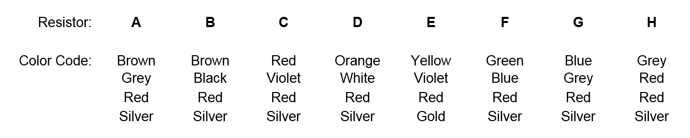
- (Note: We no longer ask students to determine resistance from the color codes) Unsure of colors of resistor stripes: Here's the list; you can tell them the correct colors (you might want to ask if any of your students are color blind), but they need to know what to do with them
- Magnet polarity
- Students use a galvanometer and coil (the same ones used in the Lenz's Law experiment) to determine the polarity of a magnet with tape covering the ends.
- Note that the galvanometer wires are crossed in their connection to the coil. Students are instructed not to change the wiring of the coil, yet many still do. Check the grading rubric for point deductions
- Common problems:
- Not much to go wrong here, unless a wire is not making contact
- Students will occasionally undo the wires; try to keep an eye out and make a note about who did it so you can deduct points later. Also, try to make sure the wires have been put back to their original configuration before another student uses that setup. I've had the problem where I didn't catch it in time, so I had to let it go and not deduct points
- Laser Wavelength
- Determine the wavelength of a red or green laser mounted to an optical bench
- Common problems:
- It's easy to bump a component on the optical bench. Students will generally tell you if they hit something. Here are the positions for the components:
- Laser: the mounting base is set flush with the left side of the track. The actual position does not matter, as long as there's sufficient room for the placement of the grating wheel (since the green lasers have a much larger heat sink)
- Grating wheel: The pointer is positioned at the 5.5 cm mark, which puts the grating at the 3.0 cm mark. The instructions warn students about this discrepancy. Also, the laser should be pointing through the 5-aperture grating on the wheel
- Screen: The front of the screen is placed at the 112.0 cm mark
- Again – students forget how to print their KaleidaGraph plots! They will choose Print Setup instead of Print Graphics. *double-sigh*
|