- Computers are needed for lab this week
- This is the only exposure University Physics students have to lens optics. As such, a brief explanation of the types of lenses is required at the beginning of lab.
- Fall 2023: This experiment was switched from Phys152 (Spring) to Phys151 (Fall) semester
- Jeff has an Excel spreadsheet to quickly check student values of focal length from their graph (enter student's measured values of q and the uncertainty in intercept)
- For the pre-lab discussion, converging and diverging thin-lenses will be available for show & tell. Pass them around to students
- Show students the pointer at the base of each lens holder; it marks the lens position on the optical bench. The object (light box) and screen positions are read from the front edge of each
- Window blocks are not needed for this experiment, which can be performed with subdued lighting. Turn off the room lights, but leave the shades up for part I (distant objects). You might need to draw the shades for part II (close objects), especially if it's a sunny day
- The blackboard notes contain ray tracings, but students will not be doing this. Those images are presented to facilitate a discussion about what will be seen in different cases
- They may be able to follow the directions for locating the virtual image (part II, steps f - j), but they most likely won't understand what they just did, or why. You'll likely have to explain what they did, one step at a time, to each group
- The focal length of the lenses have been covered to prevent student bias. Focal lengths are as follows:
- Lens A = +20.0 cm
- Lens B = +25.0 cm
- Lens C = +10.0 cm
- Lens D = –15.0 cm
- I have added instructions where they check their measured focal length, specifically for lens A since it will be used in subsequent calculations. If should be 20.0±0.5 cm to minimize their calculation grief. Note that some students will be off as much as 2 cm with their measured focal length!
- Problem: The lab windows are smeared/foggy, so you can't always produce a sharp image!
- No image is formed with lens A when p = 20 cm, since p = f in this case. I'll show students a quick ray tracing to show why this happens. Since they're using their measured value of f with the thin lens equation, they might calculate an outrageously large value for q.
- With f = 20.0 cm, the calculated values of q for the given p are:
| p (cm) |
q (cm) |
| 60.0 |
30.0 |
| 40.0 |
40.0 |
| 30.0 |
60.0 |
| 20.0 |
Undefined |
| 10.0 |
-20.0 |
-
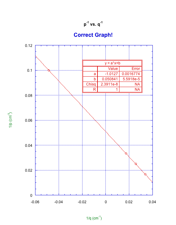
A plot of 1/p vs. 1/q is created in KaleidaGraph. Since students frequently don't label the data columns before creating the plot, and the values of p and q are close, they frequently plot the graph backwards (1/q vs. 1/p). This still gives a reasonable focal length, so it's harder to find. The correct graph will have one point in the upper left, and three in the lower right, as shown in these samples:
- Unless I successfully turn things around in the future, you'll need to talk each student through the calculation of the focal length from their graph. Remind them that this is the same type of analysis that they use each time they've plotted data!
- They plot p-1 vs q-1, so:
- Therefore, slope = -1, b = f-1 and f = b-1. Ta-dah!
- Here's what I hope students figure out in the last two discussion questions:
- How is q related to f when p = ∞? When p = ∞, p-1 → 0, so f-1 = q-1 and therefore q = f. This shows that the image of a distant object will be formed at the focal point, so that is why we use this arrangement to measure the focal length of a lens.
- You'll generally have to prompt students, "What happens to the fraction 1/p when the denominator gets very large?"
- What is the image distance when the object is on the focal point (p = f)? Solving the thin lens equation:
- This shows that no image is formed when the object sits on the focal point.
- Note that weak students will come up with 0 or ∞ for this result. *sigh*
- When everyone is finished, tip over all the flashlights. Students will frequently leave them turned on and place them face-down on the bench, draining the batteries
- Spring 2023: I've removed the part about making a telescope. They really couldn't see through it and got nothing from it
- When making the telescope (step 1c), students might find it easier to see what's happening to the image as they separate the lenses by holding the optical bench on their shoulder (like a bazooka). This is especially helpful when the lab is crowded
|