Physics 104 Set Up Instructions:
The Photoelectric Effect
(click each image for a larger view) Return
to main setup page
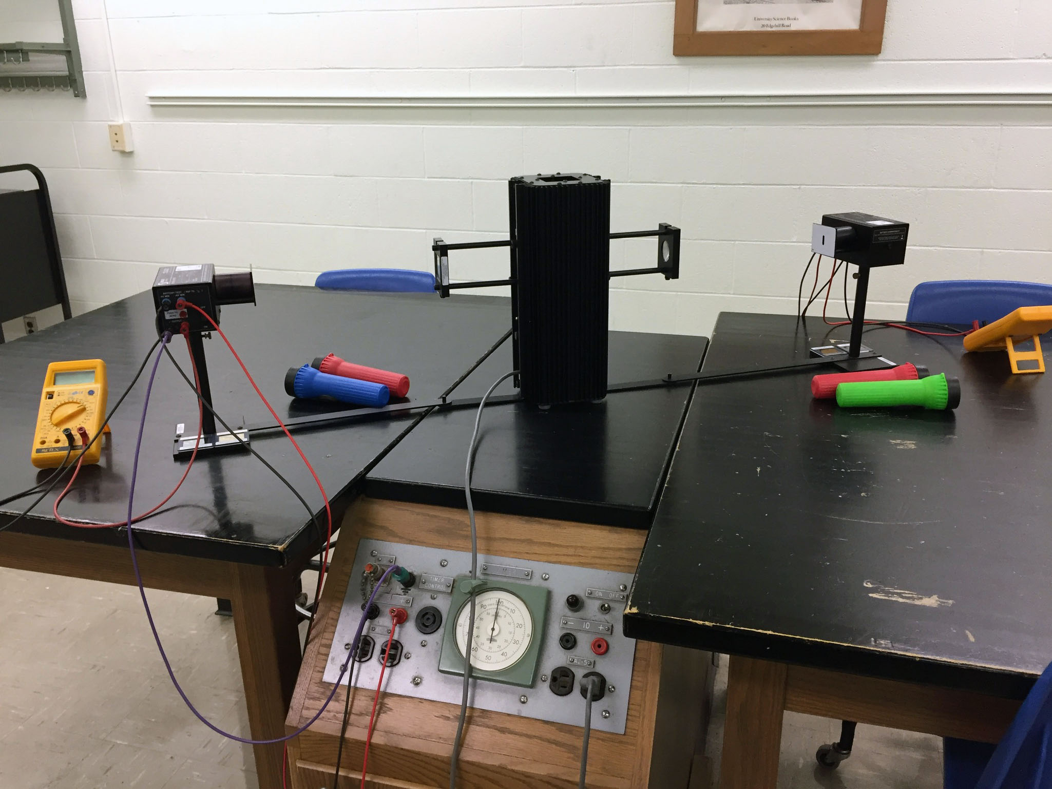
Two photodetectors per light source; Note angled position on lab bench
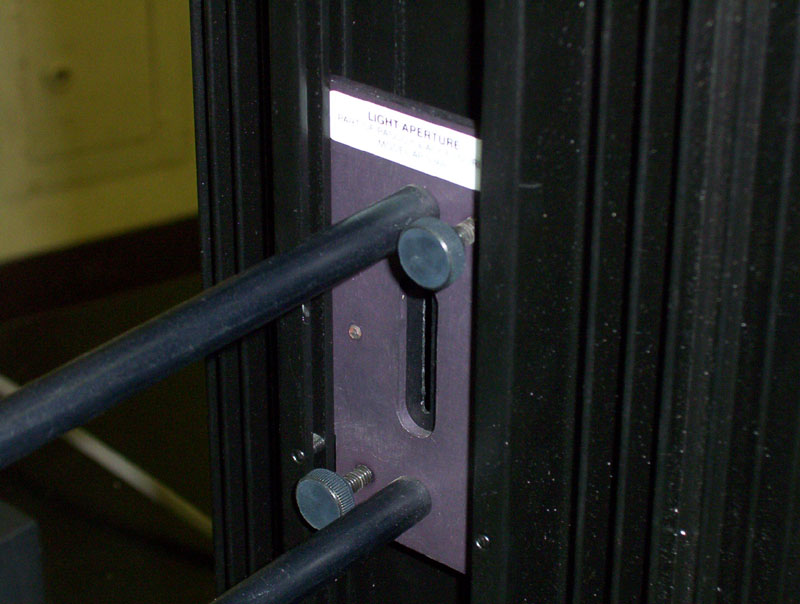
Attach aperture to the light source. . .
. . . using the middle groove. Tighten thumbscrews
The blazed diffraction grating mounts on end of aperture assembly.
Note orientation of label and thumb screw on bottom; label must be
on the same side as the wire connections on the photohead
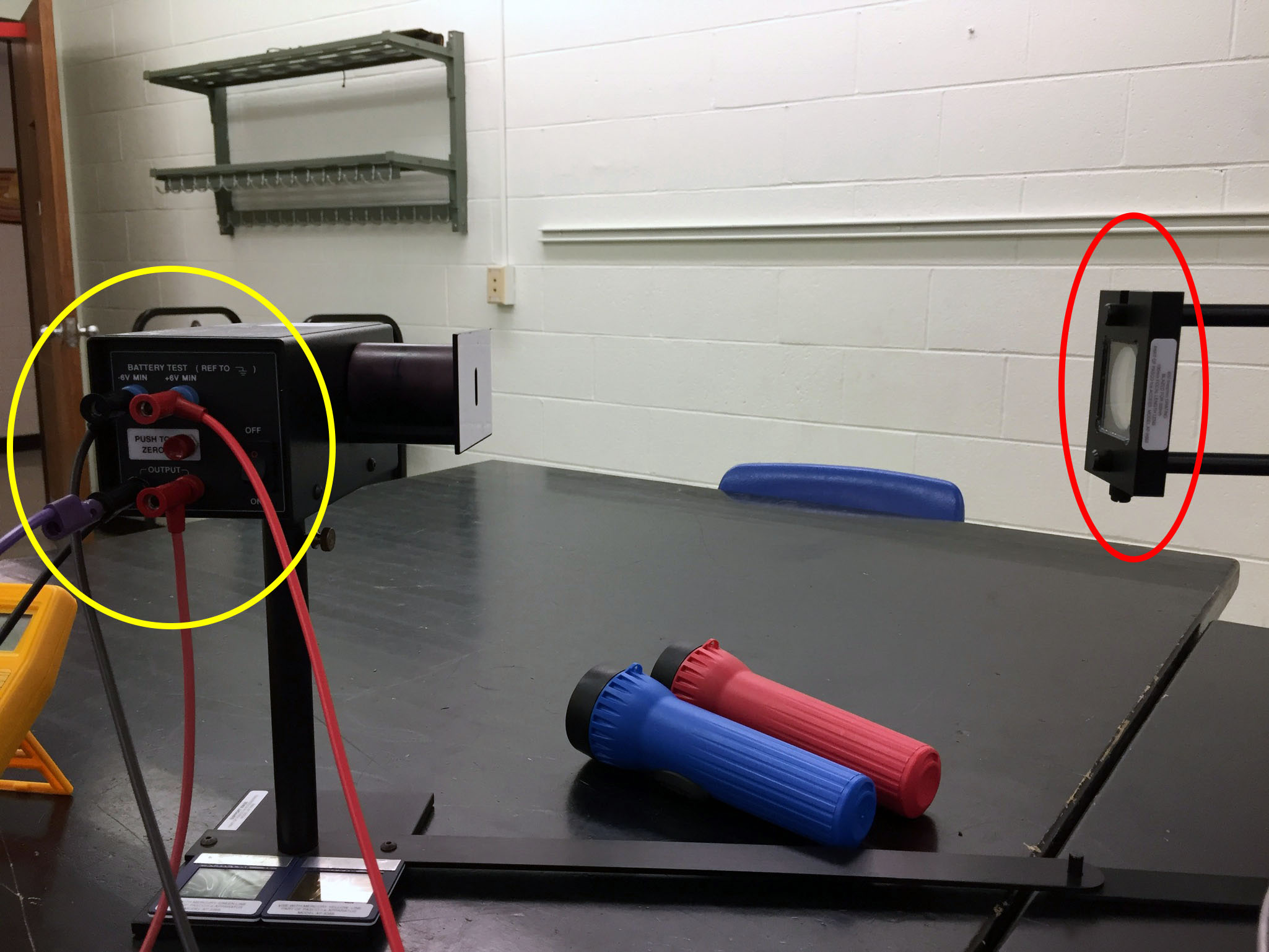
Note that label on grating (red oval) is on same
side of photohead as wire connections (yellow oval).
The grating thumb screw should be on the bottom
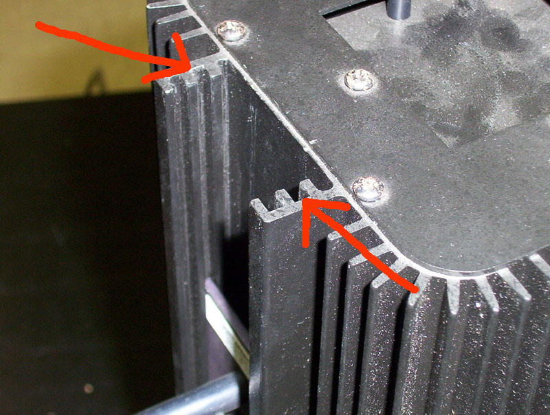
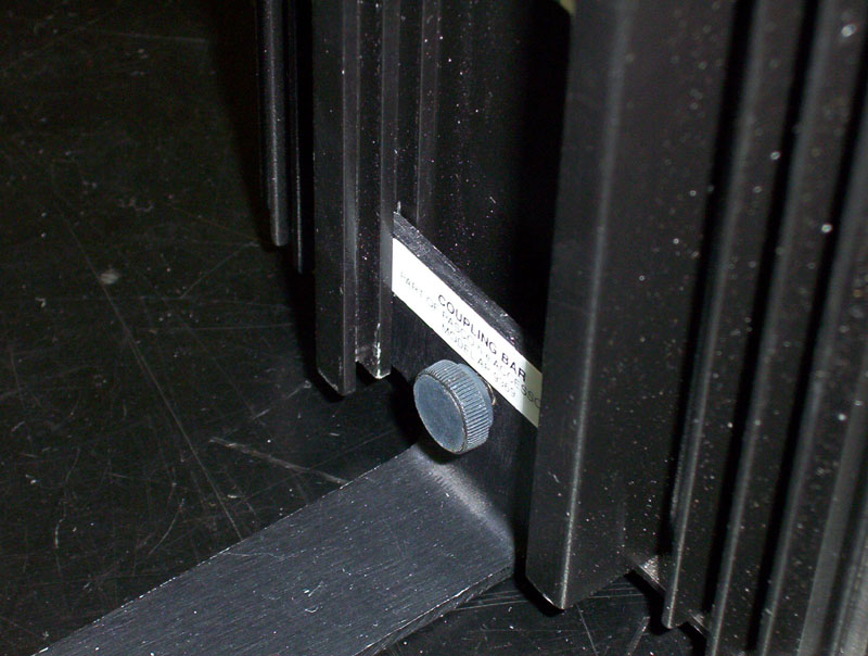
Attach coupling bar assembly, again using
middle groove. Tighten thumbscrew
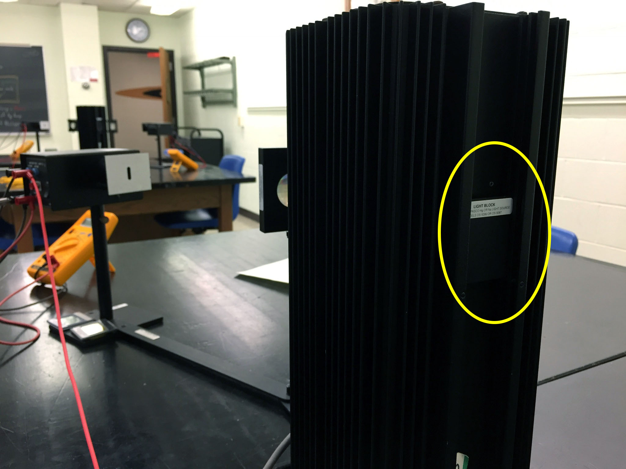
If only one side of the Hg source is used, insert a Light Block (yellow oval)
on the other side. Slide light block into the inner-most channel
Place photoelectric head on support base,
connect to coupling bar
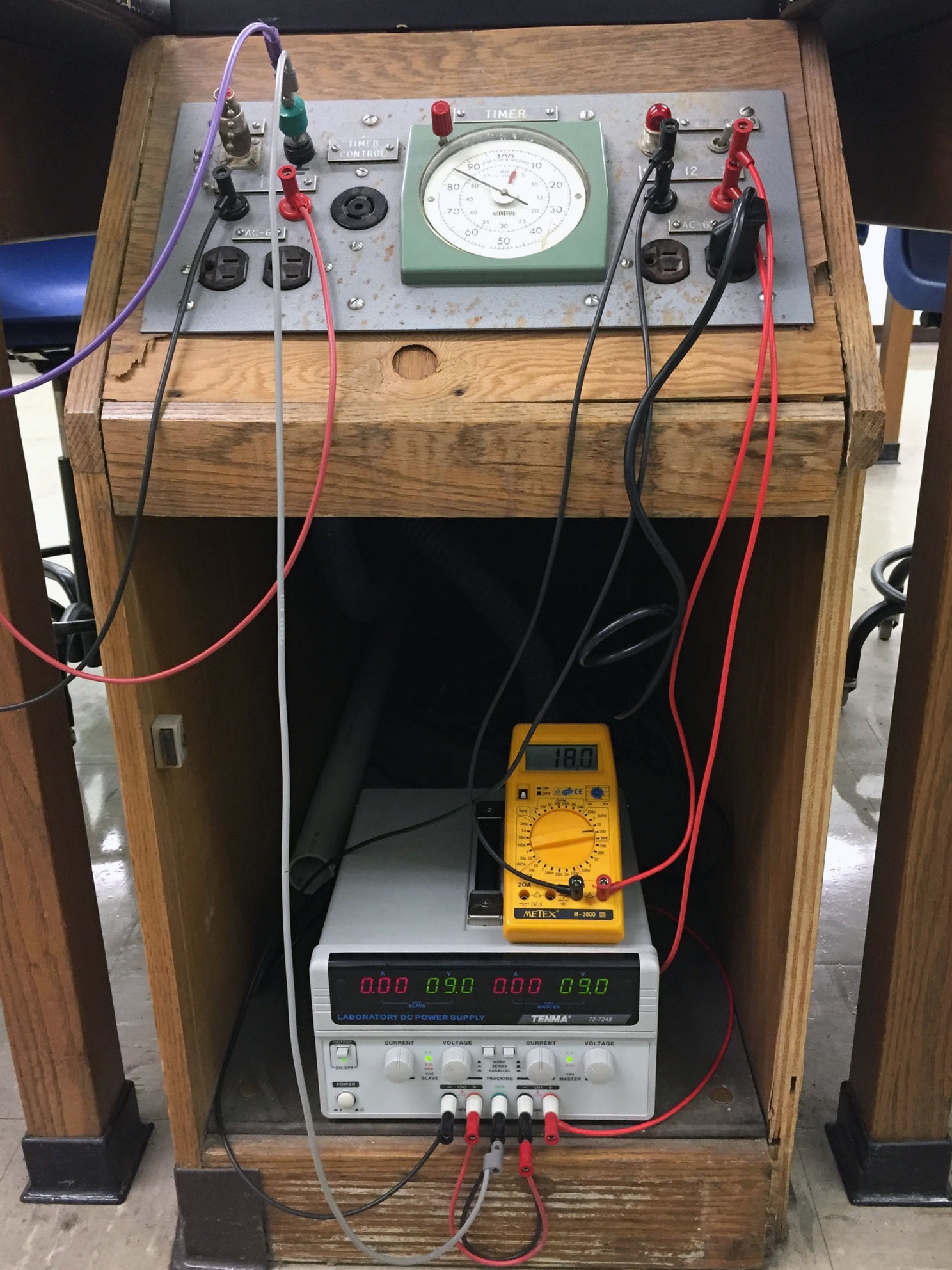
Connect multimeter; set it to 2 VDC
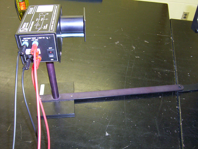
Photoelectric head connected to DC power panel
The top two wires (red & black) connect to the DC power
panel; the red & black wires on the bottom connect to the voltmeter. The purple wire connects to the panel ground
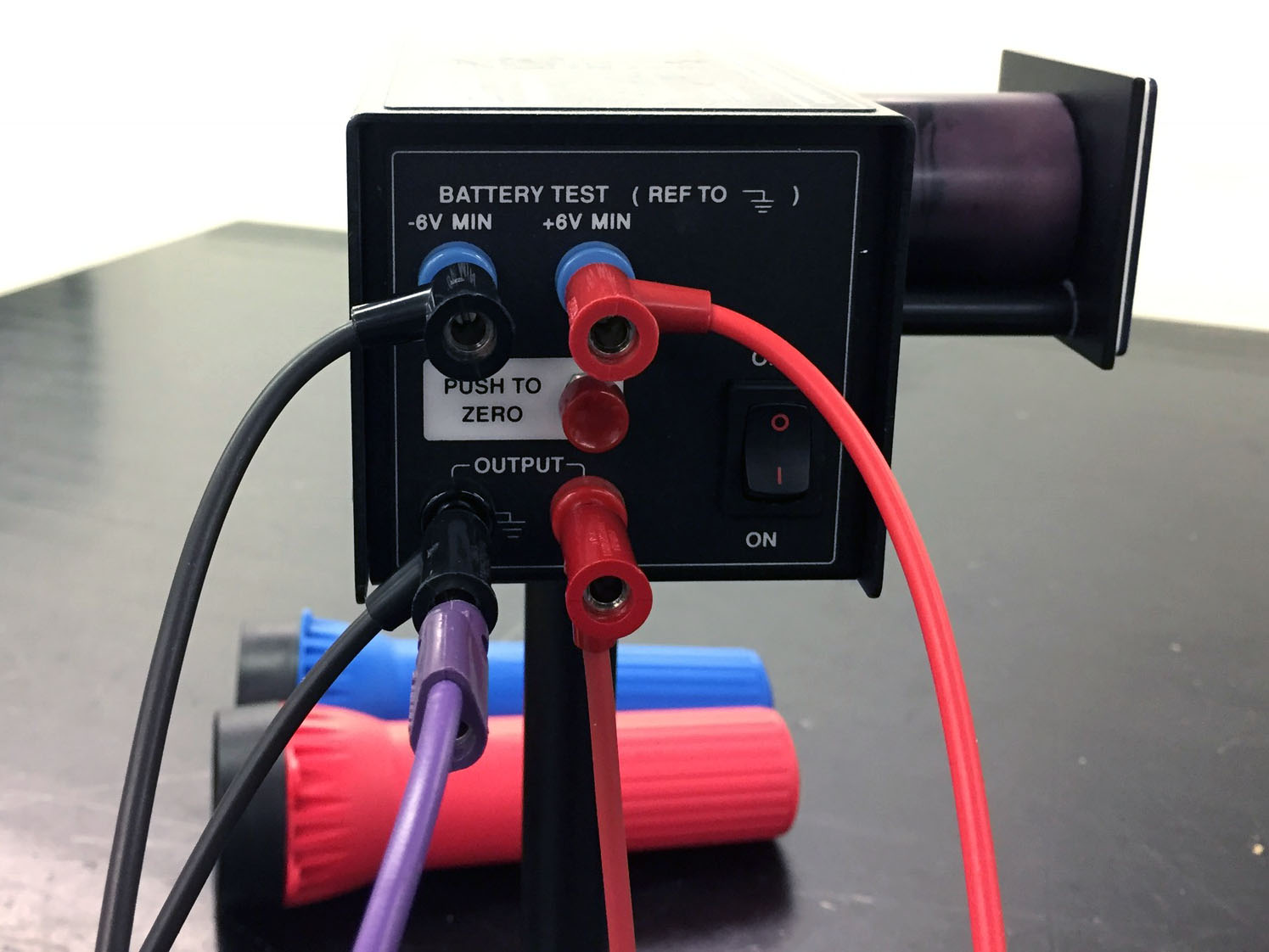
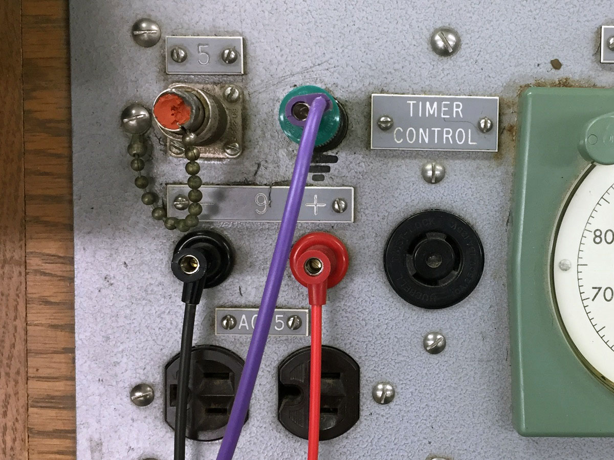
Wire connections on power panel:
Red & black to top connections on photohead; purple to ground
Place yellow and green filters on bench
Power option #1: Place one dual-DC power supply in cabinet under right-front bench
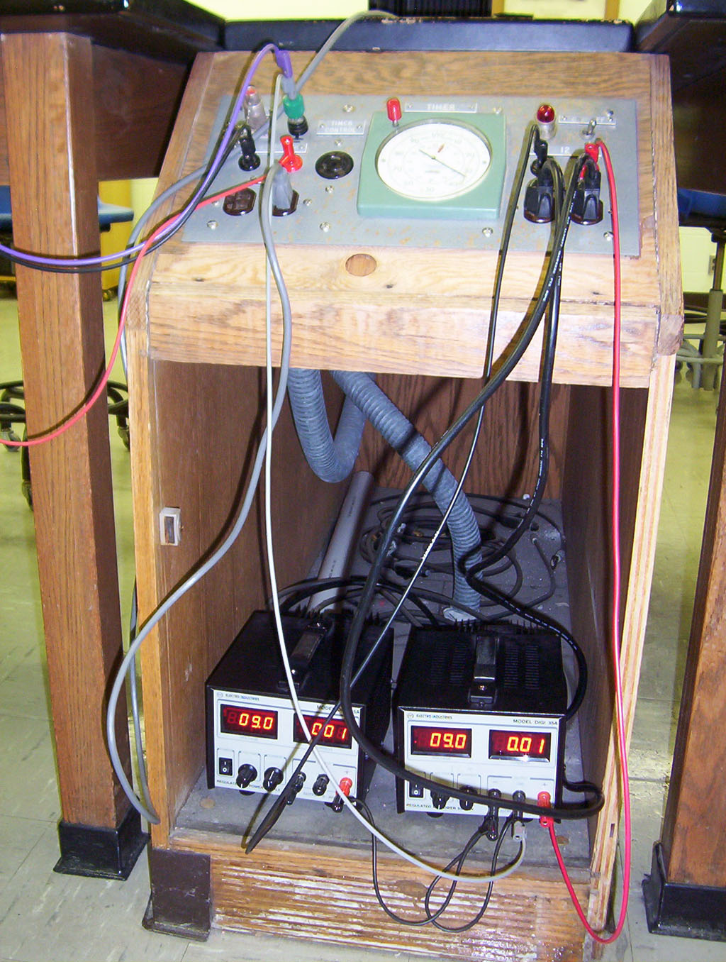
Power option #2: Place two DC power supplies in cabinet under right-front bench