
Room setup
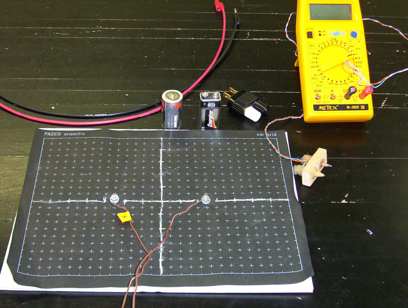
Conducting board, wires (red & black),
battery (1.5 v and/or 9 v), widow maker,
multimeter, and double-pencil probe

The wire connected to the left screw
is marked with a piece of tape

This wire (with tape) is plugged into the
red (positive) terminal of the DC power
panel on the lab bench
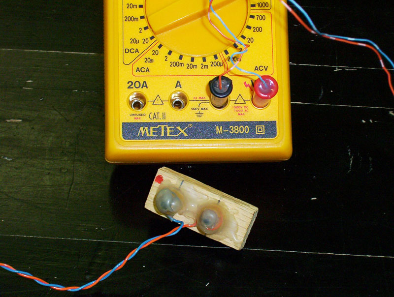
There is a red dot on the top of the
dual-pencil probe. Make sure that this
probe is connected to the positive terminal
of the multimeter
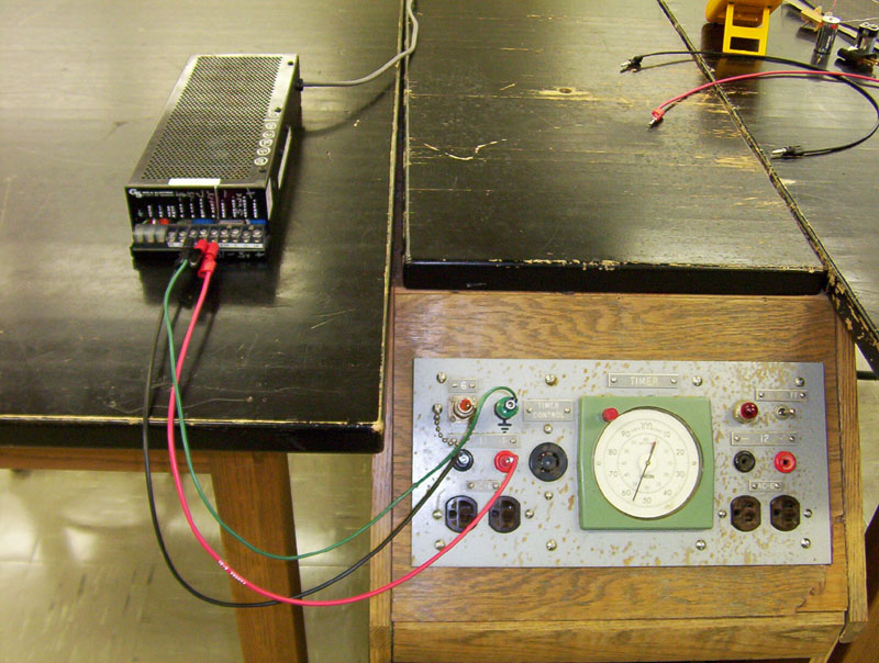
The power supply is connected to the
right-front lab bench

Three wires: red, black, green
(two blacks can be used if needed)
Use banana-to-pin connectors to attach
wires to power supply
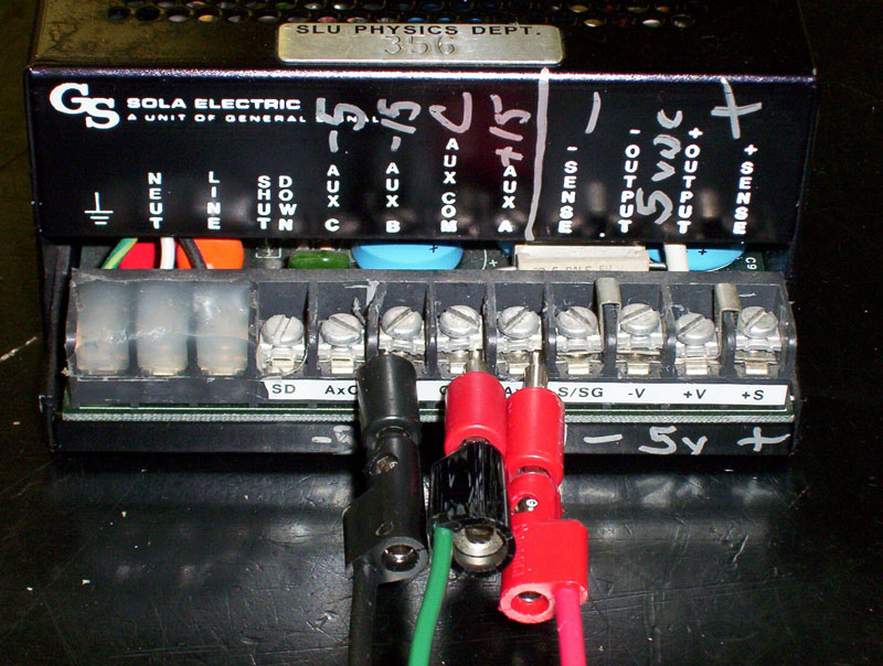
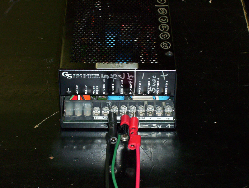
Black wire connected to "AxB" (–15 v);
red wire connected to "AxA" (+15 v);
green wire connected to "Com"
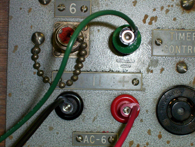
Connect wires to appropriate terminals on
the lab benc DC power panel