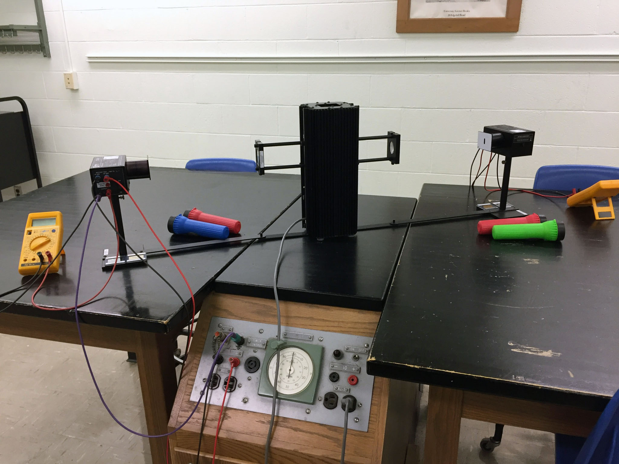
Two photodetectors per light source;
Note angled position on lab bench |
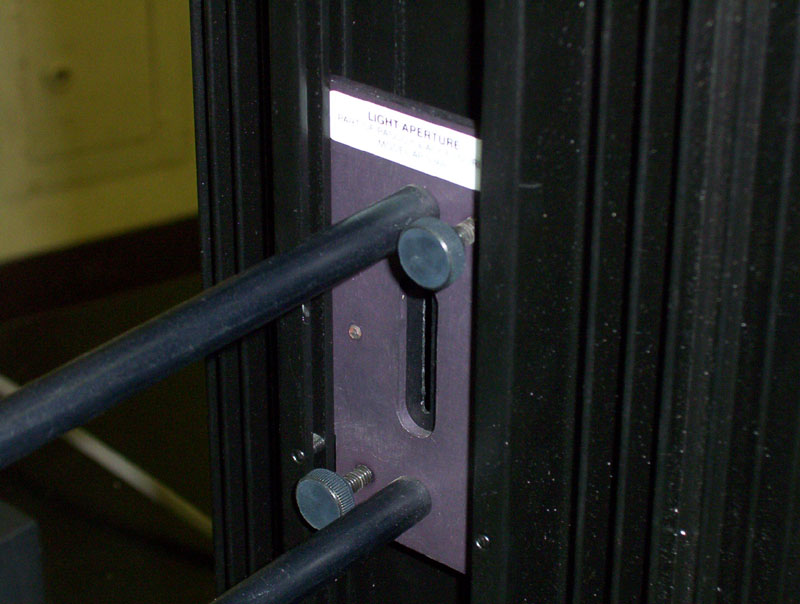
Attach aperture to the light source. . . |
. . . using the middle groove. Tighten thumbscrews |

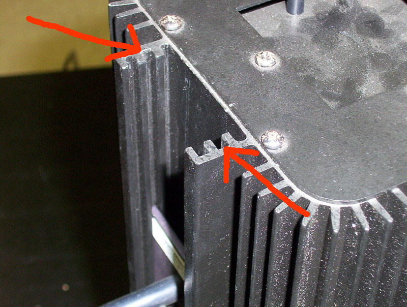
The blazed diffraction grating mounts on end of aperture
assembly.
Note orientation of label and thumb screw on bottom; label must be
on the same side as the wire connections on the photohead |
Note that label on grating (red oval) is on same
side of photohead as wire connections (yellow oval).
The grating thumb screw should be on the bottom |
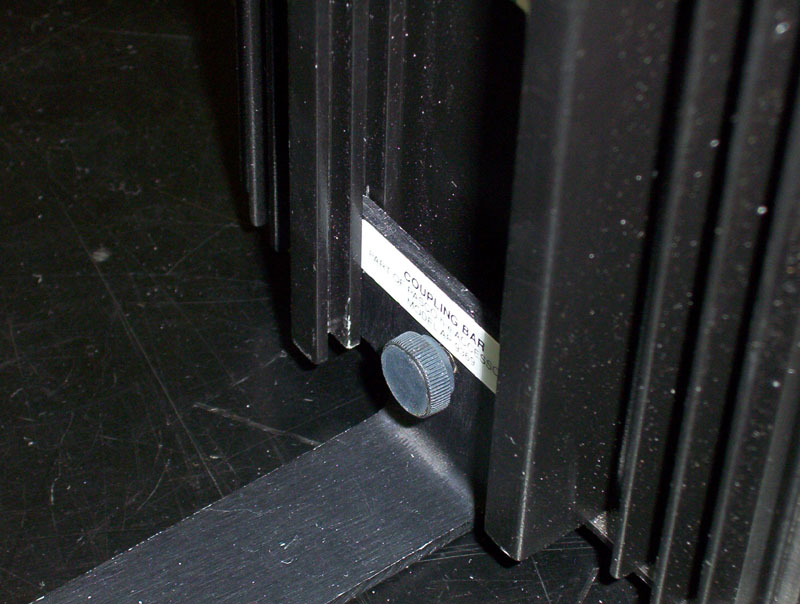
Attach coupling bar assembly, again using
middle groove. Tighten thumbscrew |
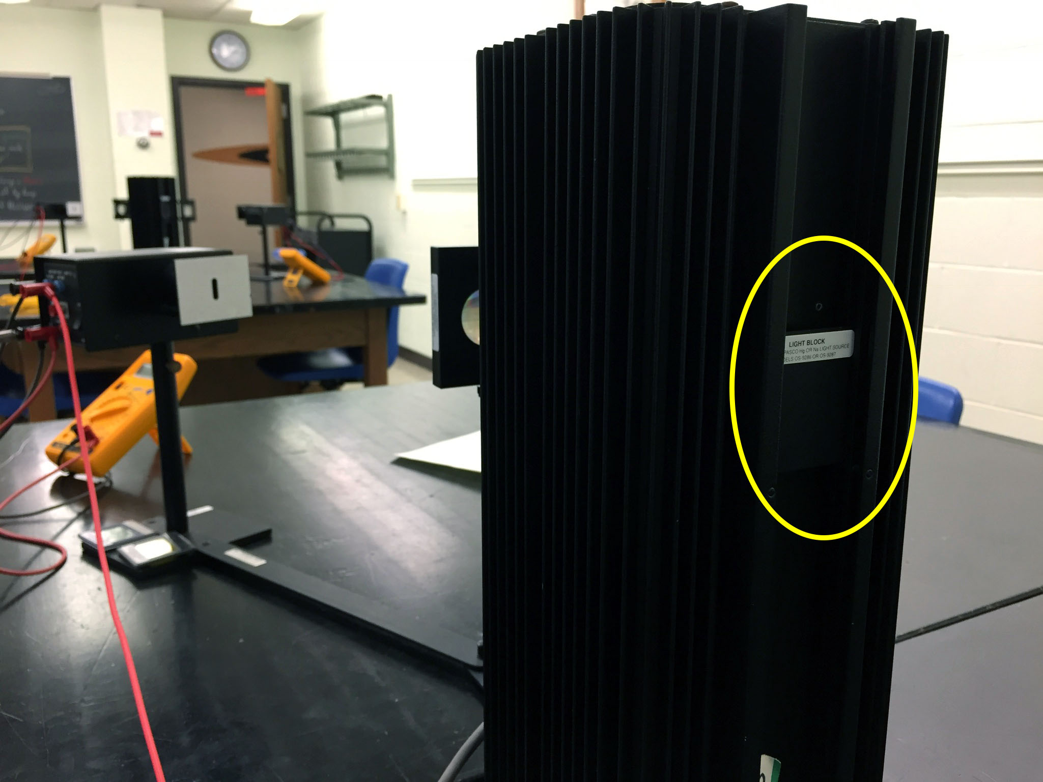
If only one side of the Hg source is used, insert a Light Block (yellow oval)
on the other side. Slide light block into the inner-most channel |
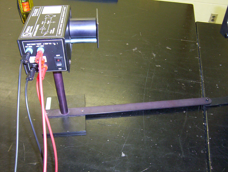
Place photoelectric head on support base,
connect to coupling bar |

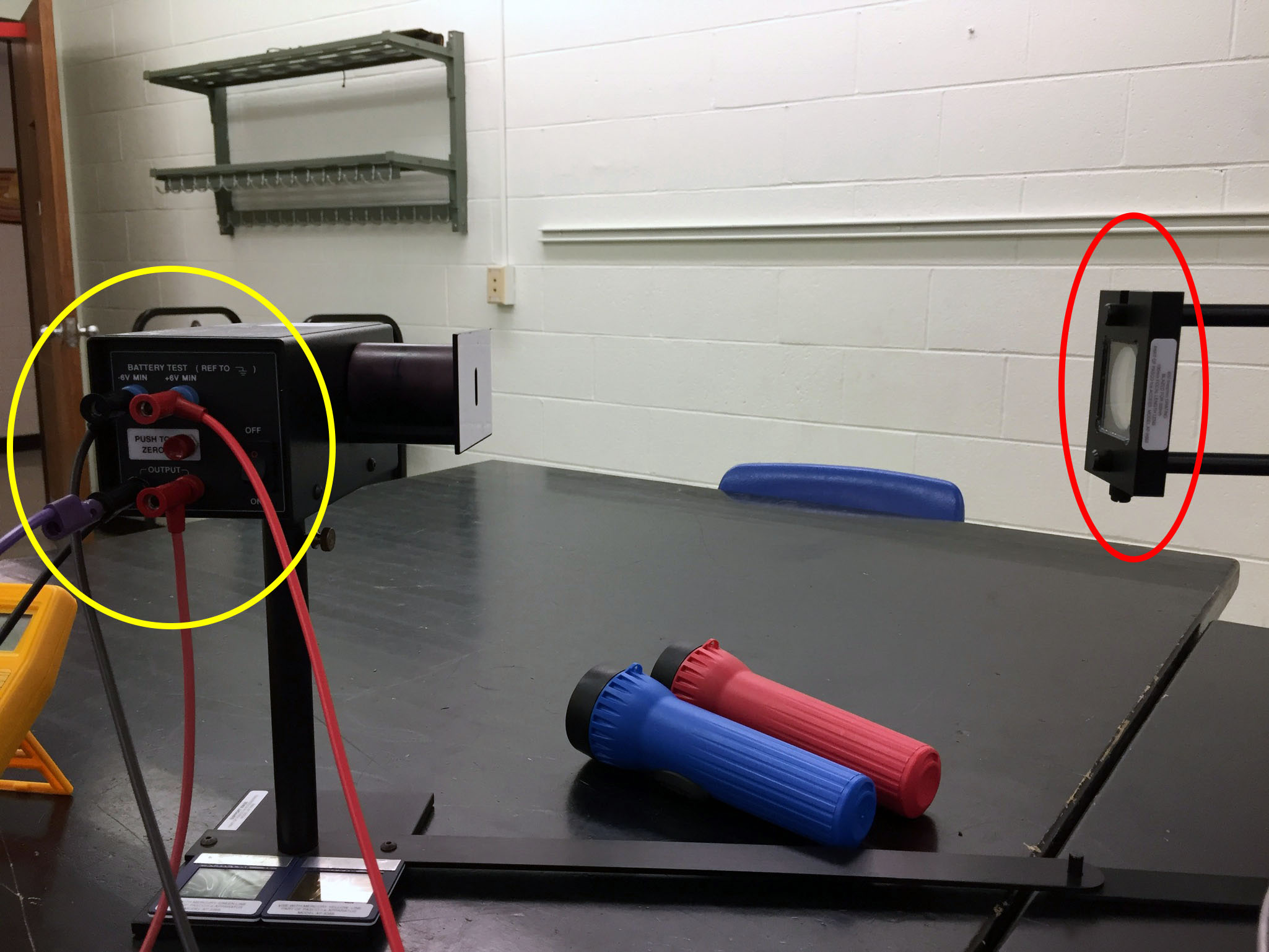
Connect multimeter; set it to 2 VDC |

Photoelectric head connected to DC power panel |
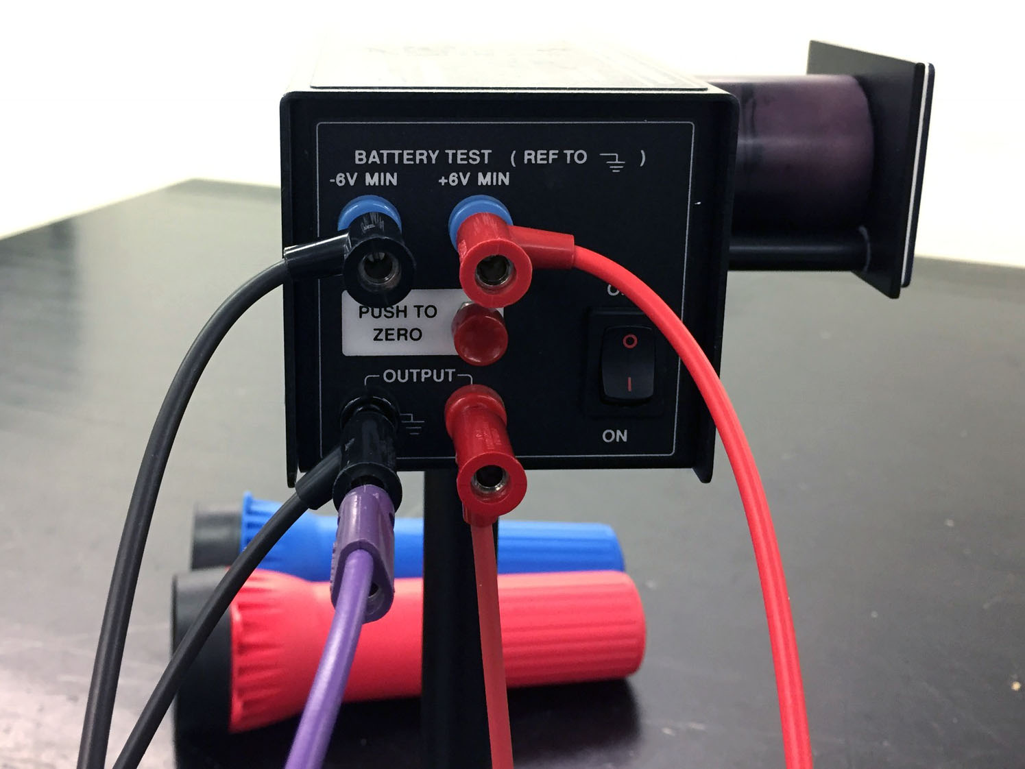
The top two wires (red & black) connect to the DC power
panel; the red & black wires on the bottom connect to the voltmeter. The purple wire connects to the panel ground |
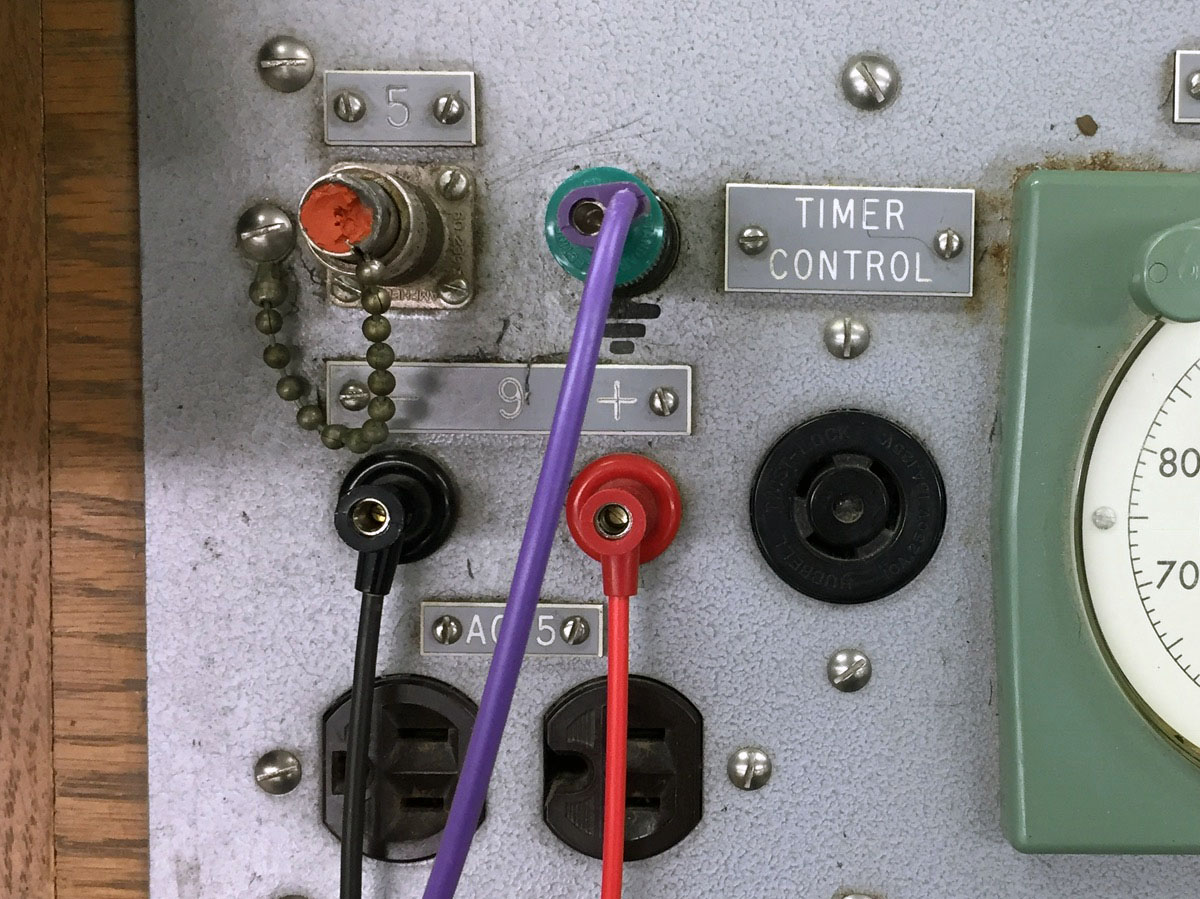
Wire connections on power panel:
Red & black to top connections on photohead; purple to ground
|

Place yellow and green filters on bench |
| Dual Power Supply Connections |
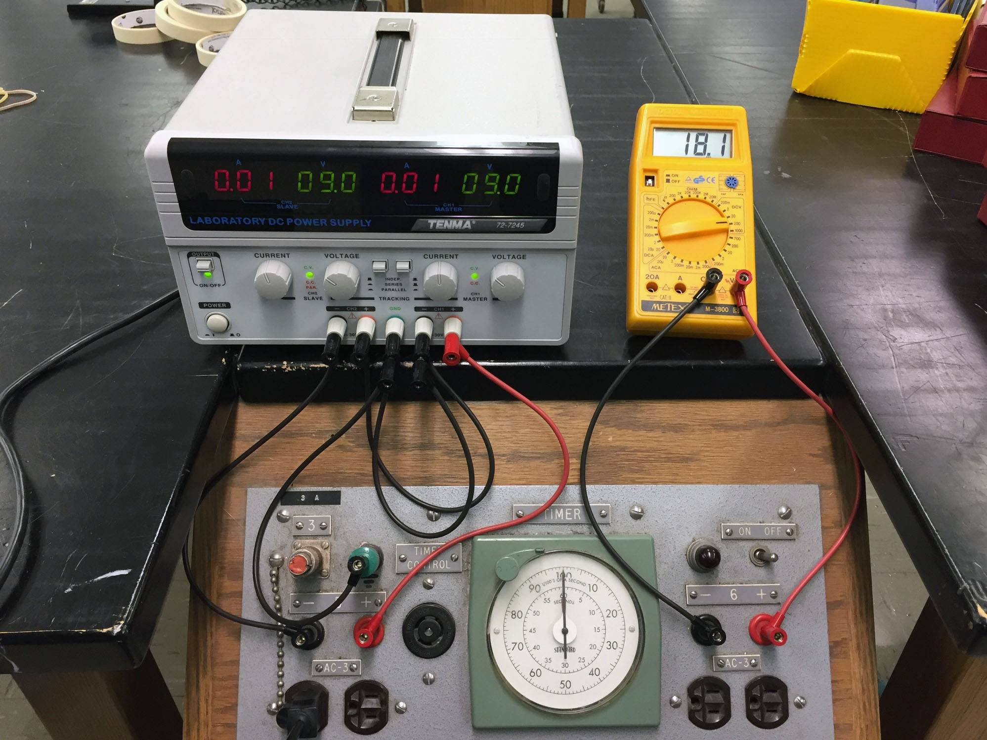
Connect DC power supply (1-dual, as shown, or 2-singles)
to bench, and set
to ±9 volts |
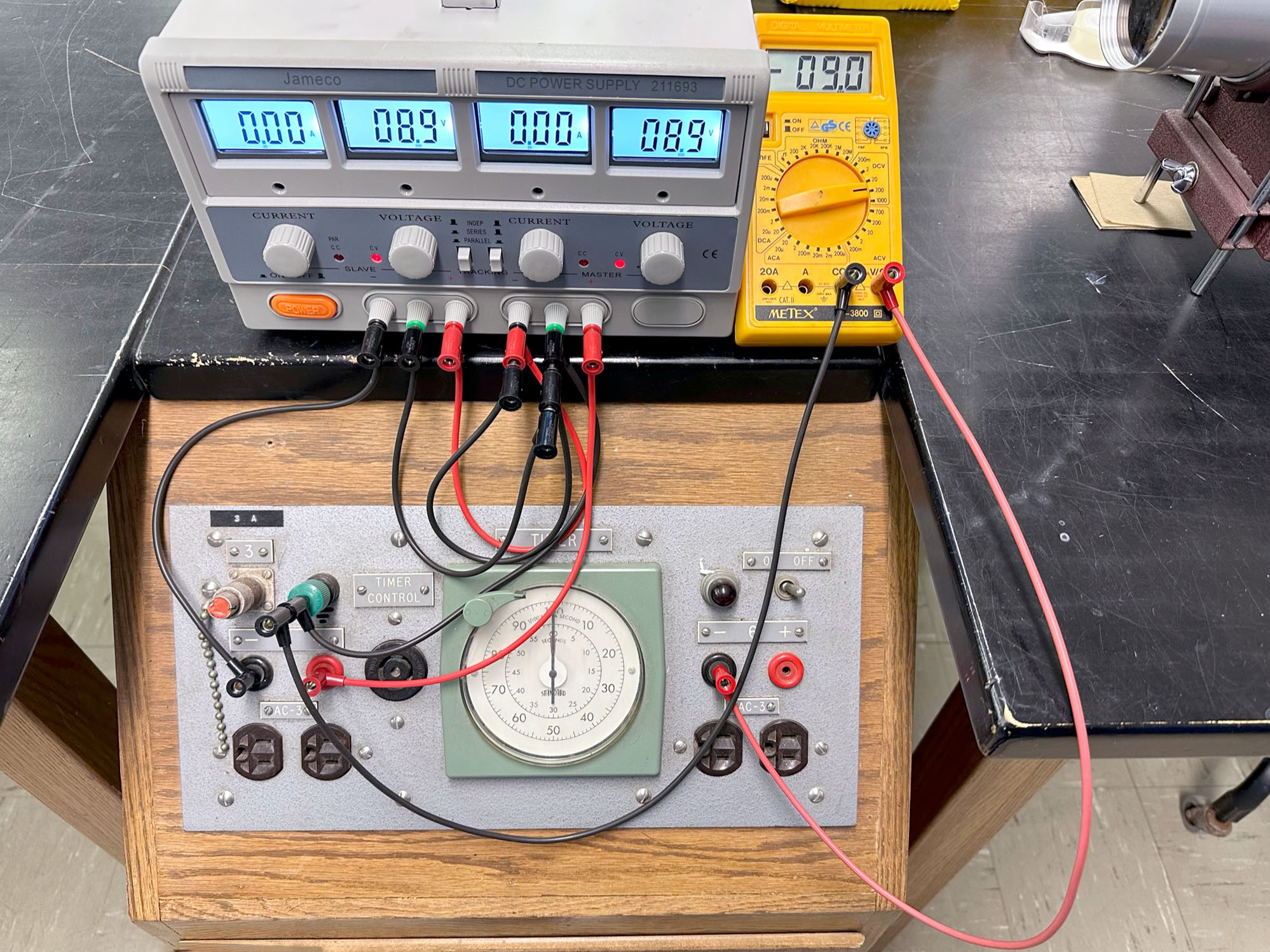
Spring 2023: I used a different dual-supply, one that has a separate ground connector for each side. I connected the two ground connectors with an additional 12" black wire and all seems to work properly |