Basic Operation of the FlexLab Power Unit:
- Up to three separate DC voltages can be supplied using the FlexLab unit. Each voltage supply section (Figure 1, within the red box) contains a voltage gauge, indicator light, two circuit breakers, voltage dial, and blue & red output connectors
- Two rows of connectors (upper & lower, Figures 1 and 2) allow the distribution of voltage to all the lab benches, according to the numbered connections along the bottom
- Each patch cable has a pin plug and a socket plug on each end (Figure 4). These are plugged into the appropriate connector in the output or distribution section (Figure 3). Note that the outermost ends of the distribution rows have connectors that accept the socket plug end (Figures 2 and 3). This makes it impossible to short out the FlexLab unit
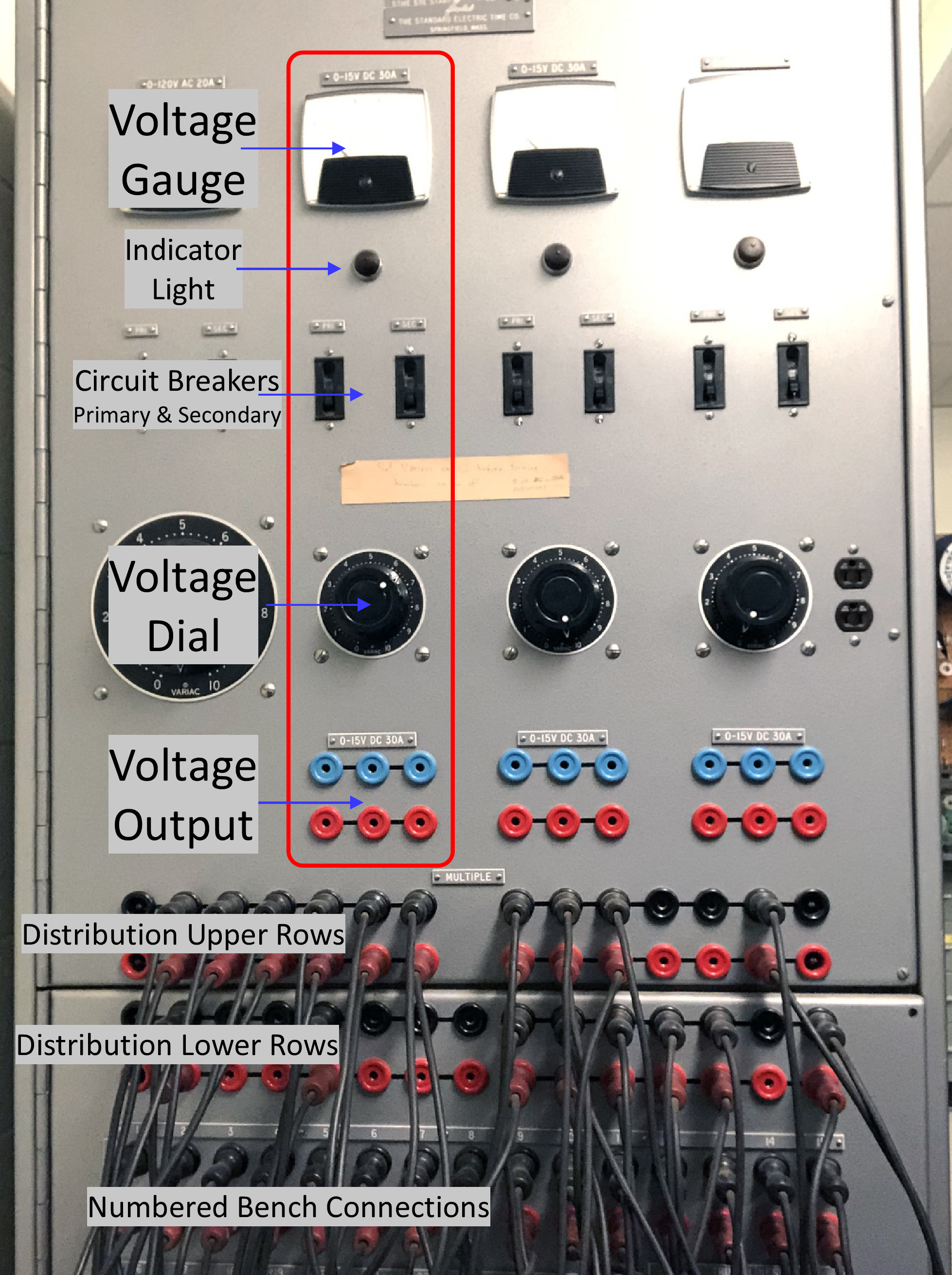
Figure 1: An annotated view of the Flexlab unit.
The large dial and white & black connectors
(obscured by labels) are for AC voltages
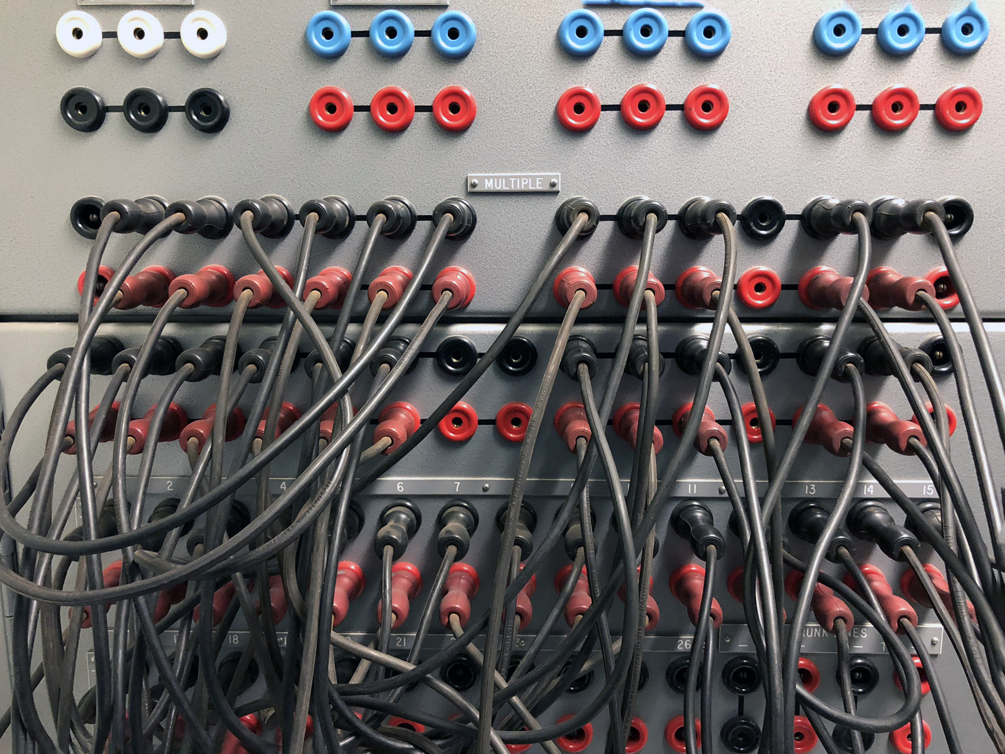
Figure 2: Detail – patch cord connections
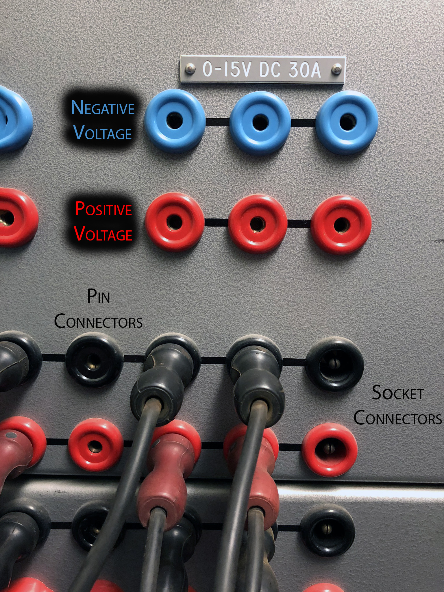
Figure 3: Detail of FlexLab connectors. The blue & red connectors
provide DC voltage from the FlexLab unit. The black & red connectors
distribute voltage to the lab benches. Note that the right-most
connectors accept the socket end of the patch cord

Figure 4: Patch cord detail showing the pin plug and socket plug ends. This makes it impossible to short out the FlexLab power supply
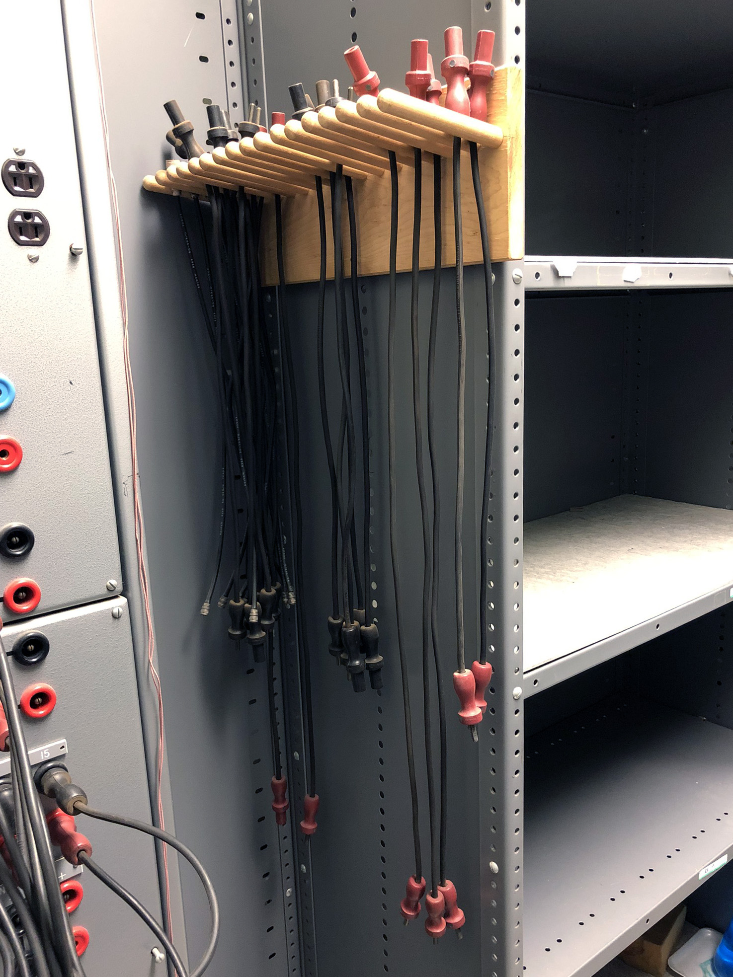
Figure 5: Patch cords are stored nearby
and available in two lengths
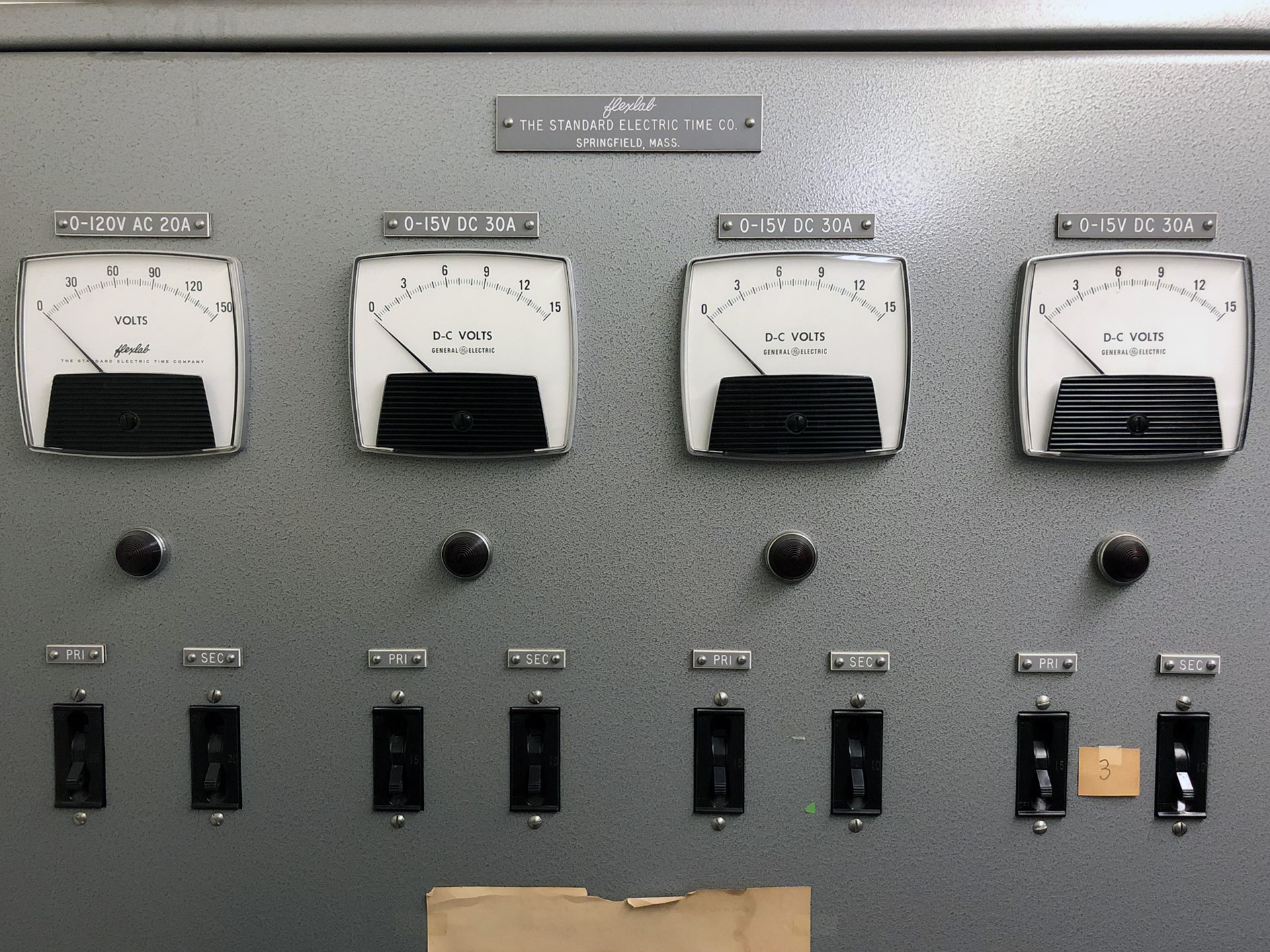
Figure 6: Detail – voltage gauges; indicator lights; primary & secondary breakers
Using the Flexlab Unit as the Power Supply to Distribute a Fixed Voltage:
- The Flexlab unit will be configured as shown in Figure 7. Make sure the circuit breakers on the FlexLab unit are open (down position)
- Connect the pin end of a patch cord from the blue & red connectors (any column) under the voltage dial to the outermost (socket) connectors on the upper distribution row
- Red = positive voltage; Blue/Black = negative voltage
- Patch cords should already be connected from the numbered bench connectors to the upper and lower distribution rows. Check these connections if you want
- Turning ON the Flexlab power supply:
- With the voltage dial to be used turned off, close the the primary (PRI) and secondary (SEC) breakers above the voltage dial by flipping up
- Turn the voltage dial clockwise slowly until you reach the desired voltage
- Use a voltmeter to check some of the lab bench connections
- Turning OFF the Flexlab power supply:
- Turn the voltage dial fully counter-clockwise slowly until the voltage is zero
- Open the primary (PRI) and secondary (SEC) breakers by flipping down

Figure 7: Configured with Flexlab unit providing voltage to Bewkes 231
Using the Flexlab Unit to Distribute a Fixed Voltage from an External Power Supply in Lab:
- The Flexlab unit will be configured as shown in Figure 8. Make sure the circuit breakers on the FlexLab unit are open (down position), and that any patch cords connected to the blue & red connectors are removed
- Connect a DC power supply to one of the lab bench connectors (I use #5 in Bewkes 231)
- Patch cords should already be connected from the numbered bench connectors to the upper and lower distribution rows. Check these connections if you want
- Do not connect patch cords from the upper distribution rows to the blue & red connectors under the DC voltage dial
- Make sure the patch cords from the connectors where the external power supply is attached (e.g. #5) is connected to one of the distribution rows
- Turn on the external power supply and use a voltmeter to check some of the other lab bench connectors
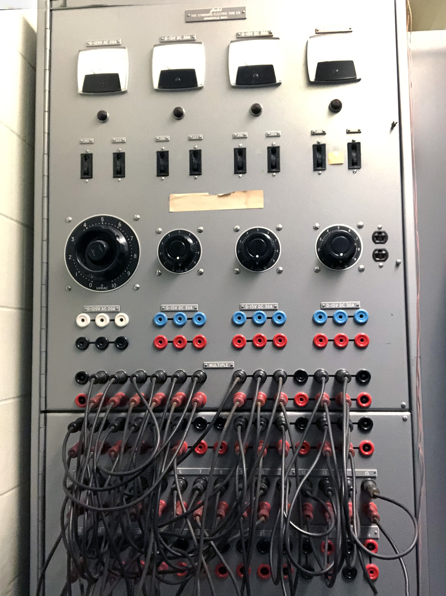
Figure 8: Configured to use a separate power supply in the lab