Building a Dual Controller Rover
Using Intel-Based Autopilots with a Hardware Multiplexer
Kevin Angstadt
angstadt@umich.edu
University of Michigan
Introduction
This tutorial provides step-by-step instructions for constructing an autonomous rover platform with dual autopilot controllers. The design provided here has been used for the AFRL-funded Trusted and Resilient Mission Operation START Project. The rover runs an Ardupilot-based software stack and supports both GPS and indoor, sonar-based localization.
Note: this tutorial is a work in progress. This document will be updated as the build process becomes more refined and bugs are resolved.
Parts List
The following parts are needed to construct the autopilot:
Autopilot
- 2x Intel+PXF Autopilot Assemblies
- 1x Marvelmind Indoor "GPS" setup (build and configuration guide coming soon!)
Amazon
- 1x Lipo Battery Charger
- 1x XT60 Charge Cable
- 1x Lipo Battery Charge Display and Balancer
- 1x Lipo Battery Bag
- 1x 16-bay battery charger
- 2x 8-pack AA Rechargable Batteries
- 3x Folding GPS Antenna Mounts (this is a generic part that shifts around between manufacturers)
- 2x 6-inch Micro USB Cable
- 1x 10-pack Servo Extension Wires, Male-Female
- 1x 10-pack Servo Extension Wires, Male-Male
- 1x 5-pack Servo Y Cables, Male-Female
- 2x Velcro Squares
- 1x Breadboard Jumper Wires, Female-Female
- 1x TP_link TL-WR940N Wireless Router
- 1x 1 foot Cat5e Ethernet Cable
- 1x Monoprice Hook & Loop Fastening Tape
- 1x XT60 Connectors
- 1x 14 AWG Wire
Hobby King
- 1x 1/16 ARR RC Car Kit (both of the following kits have worked in the past):
- 4x Turnigy 1700mAh 2S 20C Lipo Pack
- 2x FrSky DJT 2.4Ghz Combo Pack for JR w/ Telemetry Module & V8FR-II RX (We will only use the DJT transmitter)
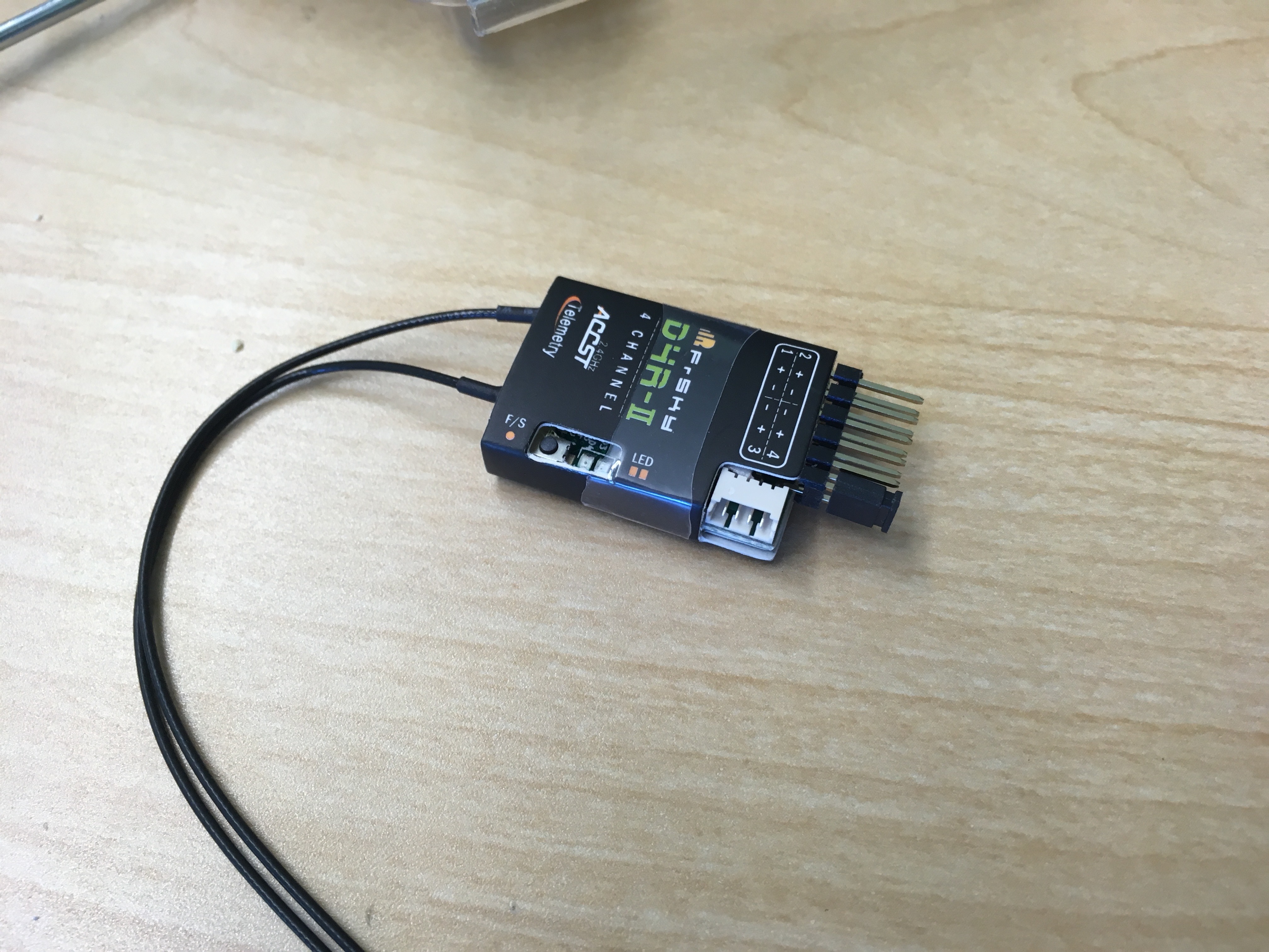
- 2x FrSky D4R-II 4ch 2.4Ghz ACCST Receiver (w/telemetry)
- 2x Turnigy 9X 9Ch Transmitter
- 2x HobbyKing Lip Voltage Checker
Digikey
- 1x SN74HC157 Multiplexer
- 1x 16 position IC DIP Socket
- 1x ATTiny85
- 1x TinyUSB programmer (This is the same programmer used for programming the RCInput Microcontroller)
- 1x 8 position IC DIP Socket
- 3x 16 position vertical header (male)
mRobotics
OSHPark
- 1x I2C Switch Circuit Board (A Sparkfun solderable breadboard could be substituted here)
3D Printed Parts
- 1x Dual 2S Lipo Holder
- It may also be necessary to modify the standoffs from the RC car. These have been helpful in the past.
Miscellaneous
- 1/4" Plywood (approx 7"x14")
- 12x M3x14 Machine Screws (available at a hardware store or through Bolts Depot)
- 12x M3 Washers
- 12x M3 Nuts
- Heat Shrink Tubing
- Cyanoacrylate (super) glue
- Drill/Drillbits/Jigsaw (for prepping the plywood)
- Phillips Screw Driver
- Wire Cutters
- XT 60 connectors, 14 AWG wire, Heat Shrink Tubing
Construction
Assemble I2C Switch Circuit Board
For this step, you will need a copy of the Arduino IDE installed and configured to program ATTiny85 microcontrollers. A helpful guide may be found here.
- Solder the 8-position and 16-position IC DIP socket onto the circuit board
- Break off 10 4-pin sections from the 16-position header and solder to the board (it may be helpful to super glue groups of three headers together before soldering)
-
Clone
i2cswitchArduino Sketch repository:git clone git://github.com/kevinaangstadt/i2cswitch
-
Launch the
i2cswitchproject in Arduino. -
Ensure that the following settings are selected in the Tools menu:
- Board: ATTiny25/45/85
- Processor: ATTiny85
- Clock: Internal 16 MHz
- Programmer: USBTinyISP
- Insert the ATTiny85 in the TinyUSB programmer and attach to computer
- Select Tools > Burn Bootloader. Check the error logs to verify that this completes successfully.
- Select Sketch > Upload to flash the firmware. Check the error logs to verify that this completes succesfully.
- Insert the ATTiny85 into the 8-position DIP header on the I2C Switch circuit board. Be sure to verify correct orientation.
- Insert the Mux into the 16-position DIP header on the I2C Switch circuit board. Be sure to verify correct orientation.
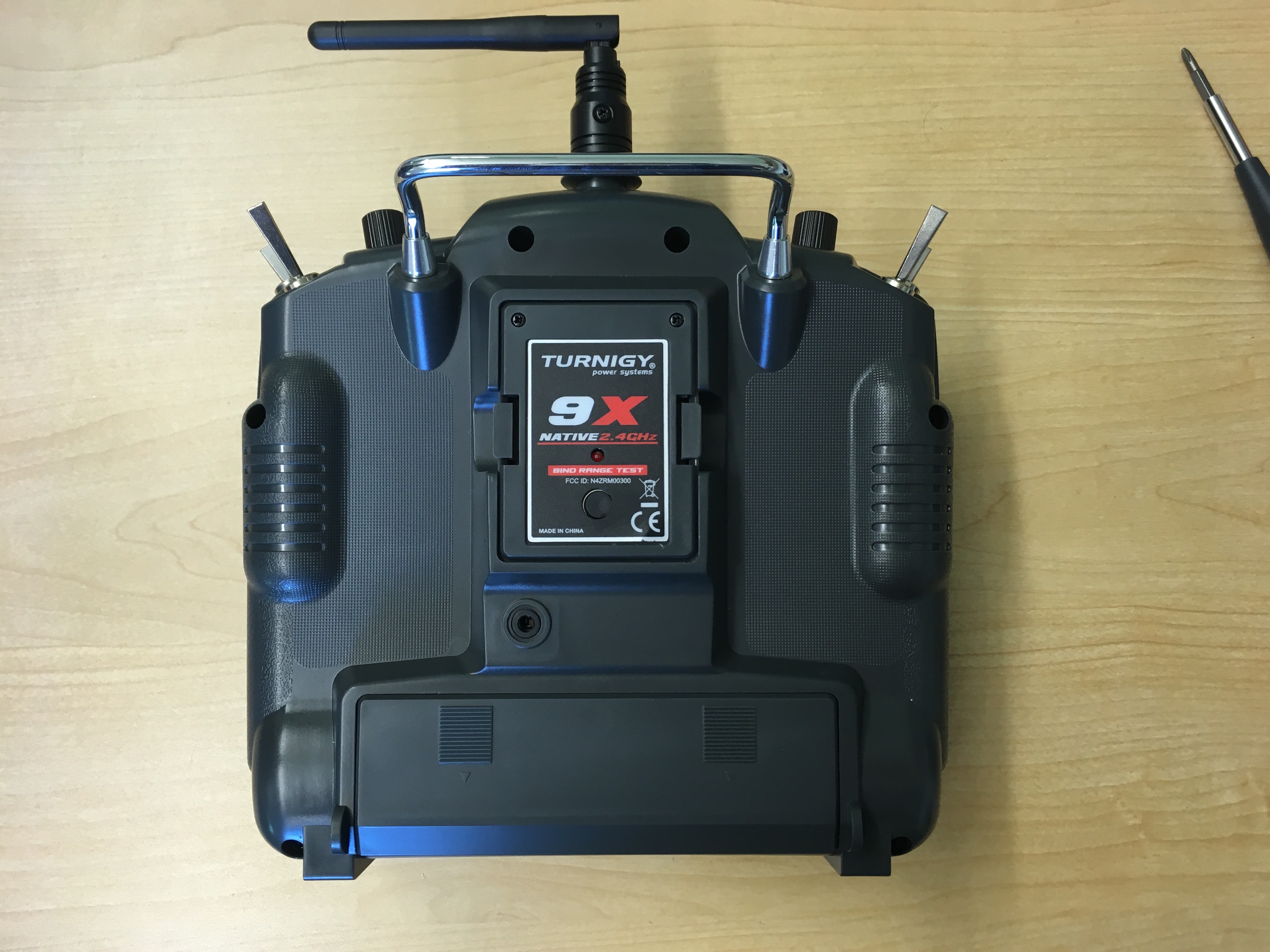
Modify RC Controllers
We will now modify the Turnigy RC controllers to use the DJT transmitter and receiver.
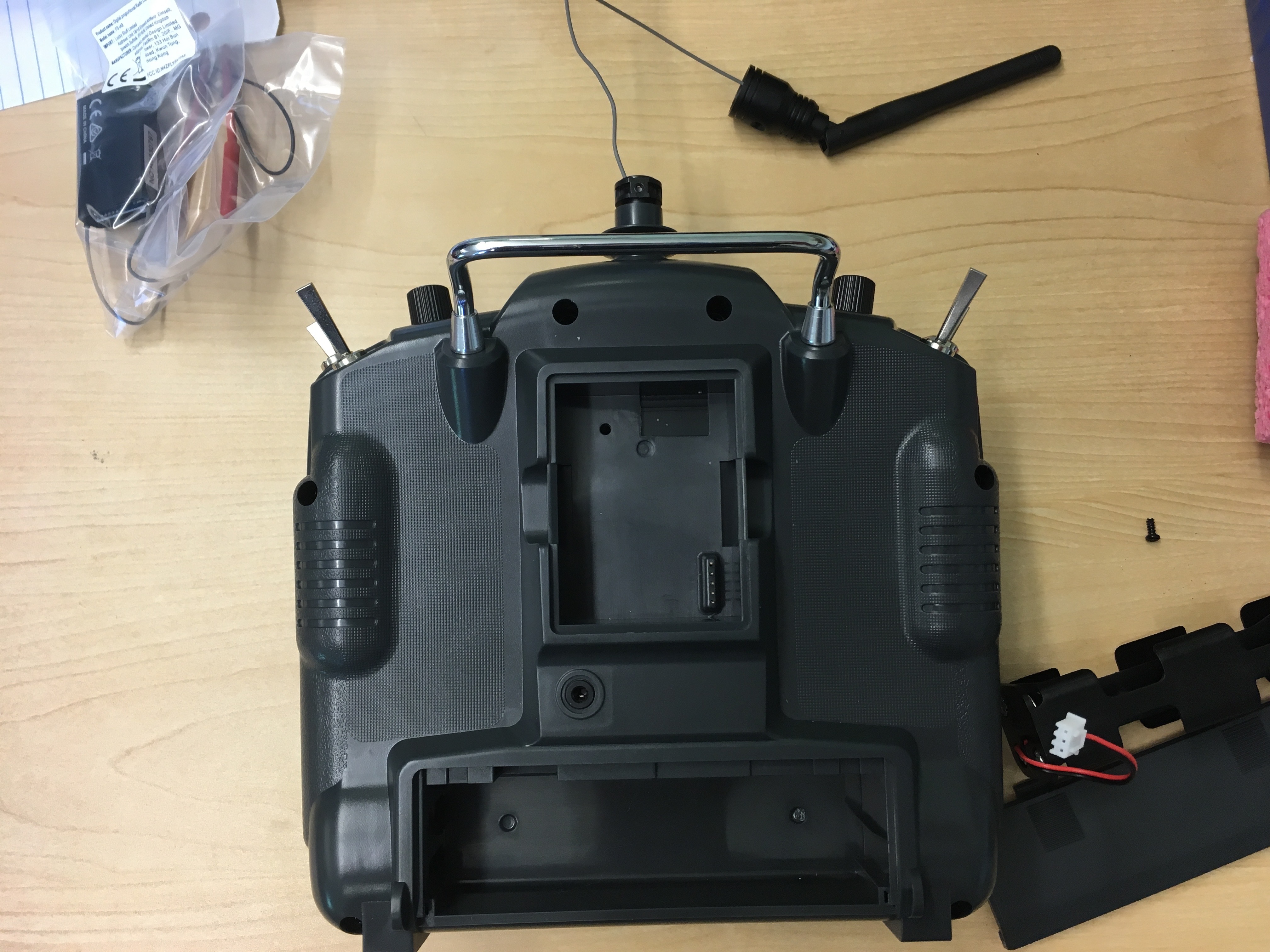
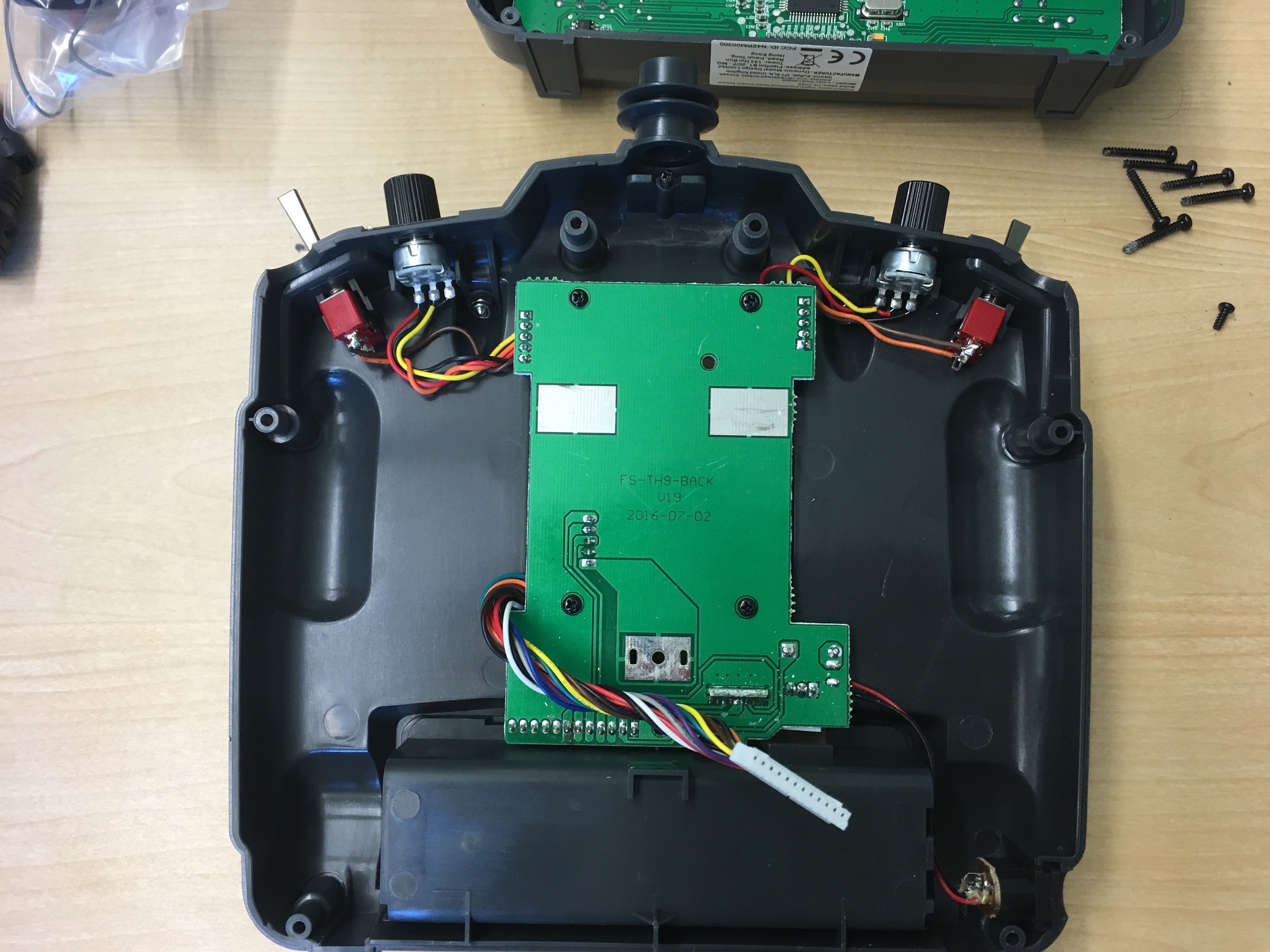
- Pop the 9X transmitter out from the back of the RC controller. Be careful! There is a wire attached to the antenna.
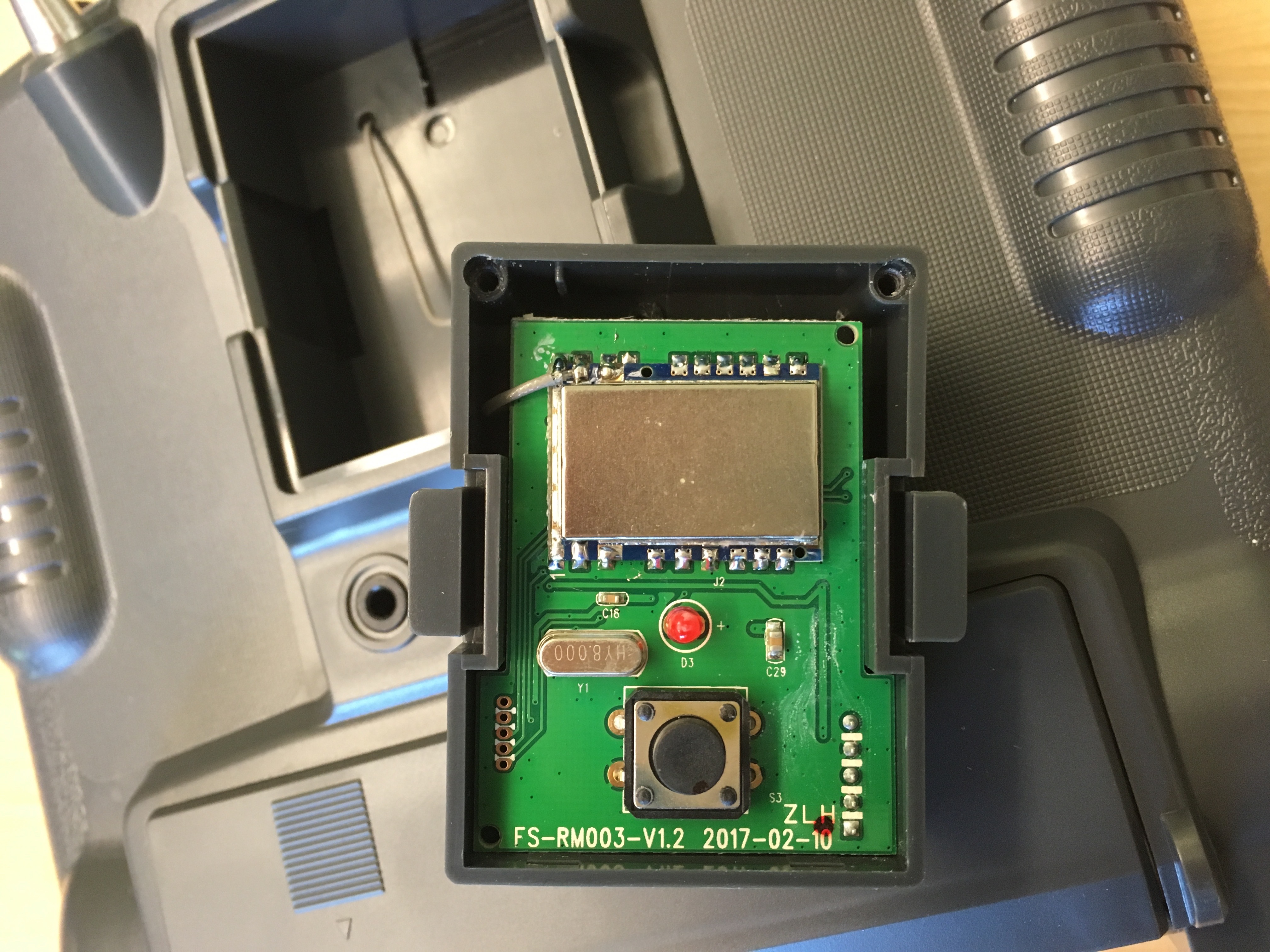
- Remove the two screws at the top of the transmitter to reveal the interal circuit board. Desolder or cut the antenna wire. The antenna may now be removed using the screw on the base.
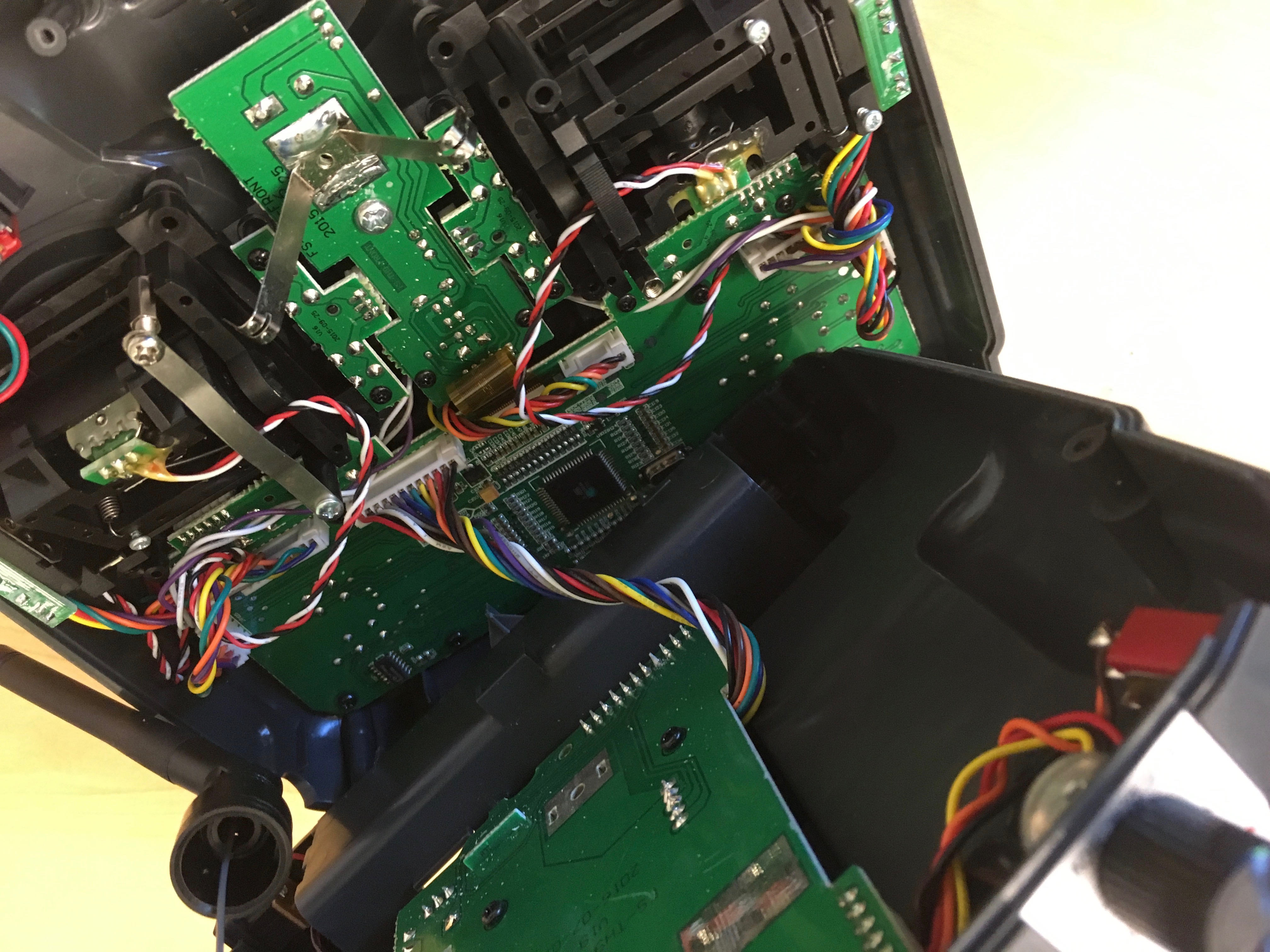
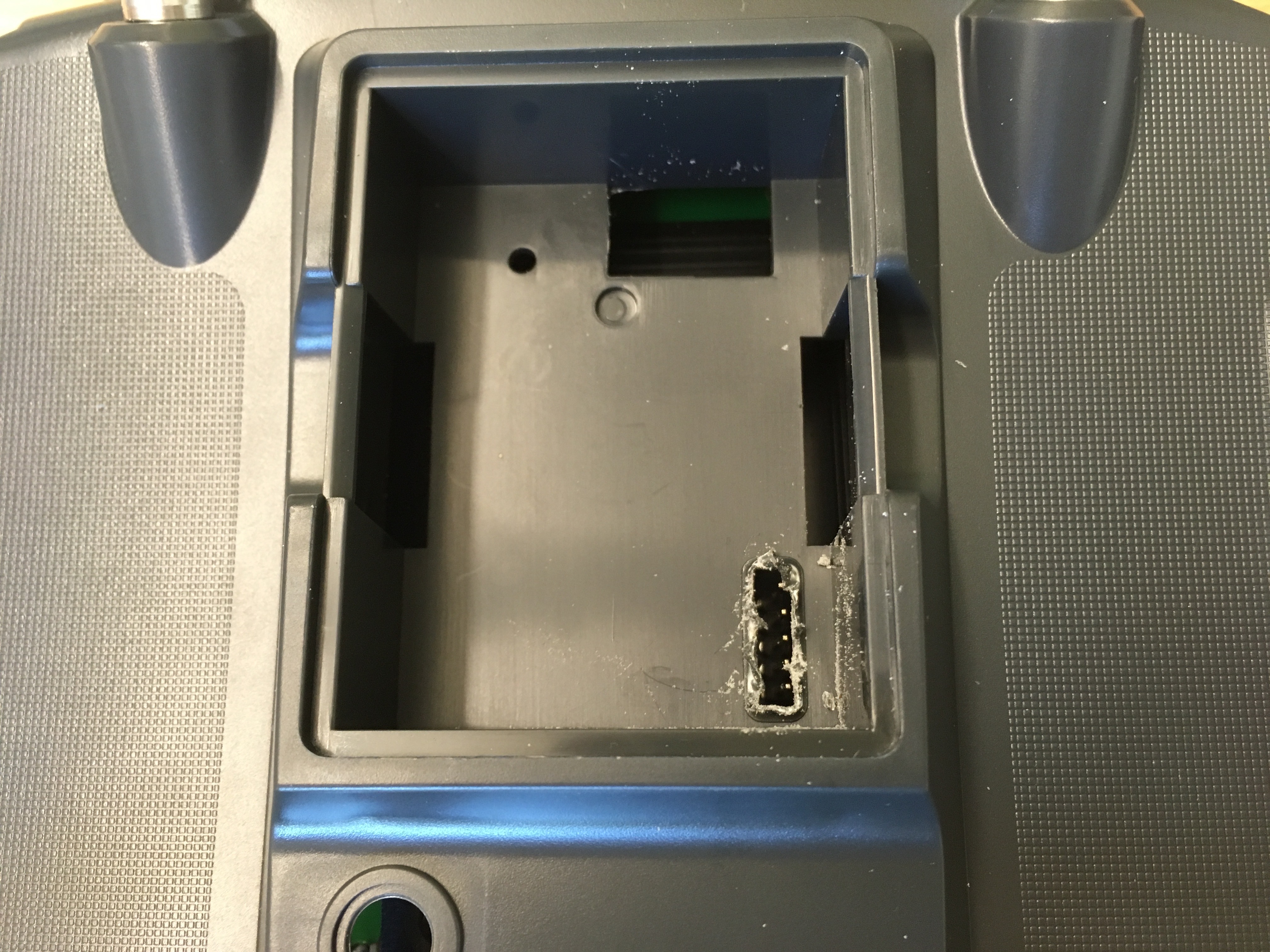
- We now need to remove the plastic around the transmitter pins on the controller. Remove the six screws holding the back of the controller to the front. Detach the circuit board and remove from the back case to protect while trimming the plastic. Trim the plastic away using wire cutters (or some other tool).
- Reattach the circuit board and close up the transmitter.
- Insert DJT transmitter
- On the D4R-II receiver, place a jumper between pins 3 and 4 to enable PPM mode.
- Follow the directions for pairing the transmitter and receiver.
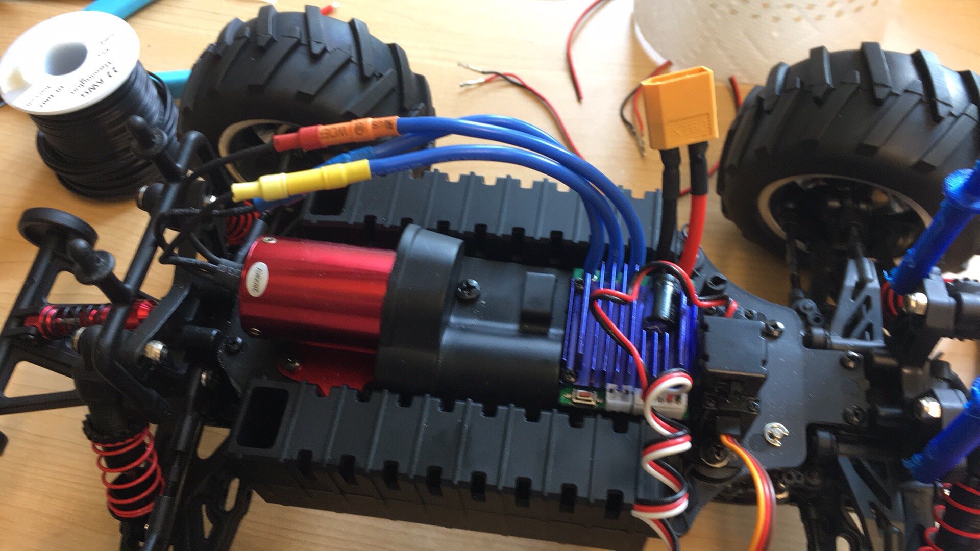
Modify Rover Base
-
Take a look at how the RC car is constructed. What sort of battery hookups are there?
-
2 connectors in series: Cut these away and add XT60 connectors
such that the power modules for the autopilots may be places between
the batteries and the motor controller.
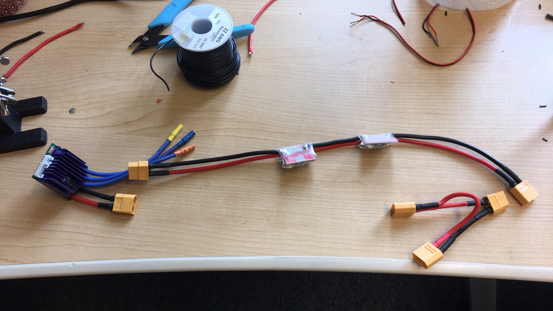
- 2 connectors in parallel: No action needed
- 1 connector: Fabricate a harness with XT60 connectors and 14 AWG wire that places the batteries in parallel
-
2 connectors in series: Cut these away and add XT60 connectors
such that the power modules for the autopilots may be places between
the batteries and the motor controller.
- Take a look at the power modules for the autopilot. If the wiring is less than 14 AWG, replace. You may choose to combine the two modules into a single unit.
- Recent RC car platforms have required alternate standoffs to allow for attaching the plywood base. Some options that have worked well with our rovers are provided in the parts list. If using, print and attach to the car chassis.
- Cut out plywood for electronics base. We find that a 7"x14" platform with cutouts for the steering wheels works well. Drill holes for the four standoffs from the RC car chassis, and cut a hole in the middle for battery and servo control wires. (See photo below for electronics layout for a rough guide of hole placement.)
- Secure base to chassis using the cotter pins provided with the chassis.
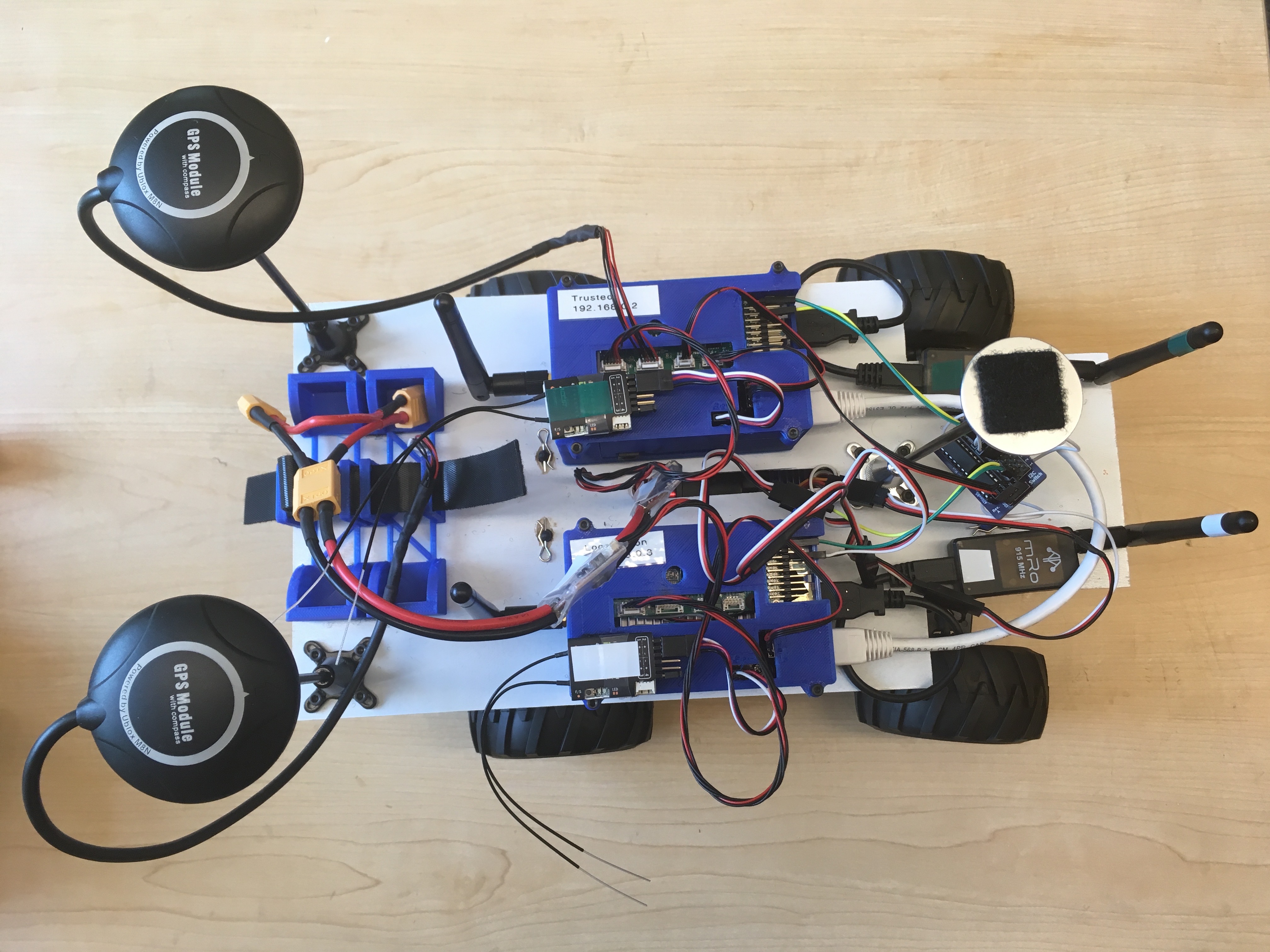
Attach Electronics to Base and Connect Components
- Plan out locations for battery holder, GPS stands, autopilots, and telemetry radios on the base.
- Attach the GPS stands using M3 bolts, washers, and nuts. The remaining parts are attached using velcro squares.
- Attach GPS antennas to the stands using velcro and connect to autopilots
- Attach RC receivers to the tops of the autopilots with velcro and attach to the RCInput circuit boards using channel 1. Be sure to line up the pins correctly.
-
Attach the power modules to the autopilots and hook into the motor
controller system of the RC car. Be sure to connect these in
series/parallel as the power system on the car dictates. Note that all
systems must share a common ground.
Danger! Incorrect configuration can lead to electronics damage, magic smoke, and possibly fire.
- Attach the I2C Switch to the trusted autopilot using an I2C Breakout cable.
-
Attach the signal wires from channels 1 and 3 of the locomotion autopilot
to signal lines on
Input Aof the I2C Switch using breadboard jumpers -
Attach the singal wires from channels 1 and 3 of the trusted autopilot
to signal lines on
Input Bof the I2C Switch using breadboard jumpers -
Connect the steering servo to the output associated with channel 1 on
the I2C switch. Connect the motor input to the output associated with
channel 3 on the I2C switch.
If the RC chassis BEC is not 5V (as in the Bad Bug), we've avoided attaching the positive and ground from the motor controller BEC to the I2C switch. Instead, we make a jumper between the servo and the motor controller for power and just attach the signal wires. Given the design of the I2C switch circuit board, this shouldn't cause any problems, but we chose to isolate the 6V BEC for additional protection.
- Connect and ethernet cable between the two autopilots.
The following is a proposed layout we have used for several rovers:
Configure WiFi
- Turn on the WiFi router and connect using the SSID and password listed on the sticker found on the bottom of the unit.
-
In a web browser, navigate to the configuration pages (typically
192.168.0.1for TP-Link routers), login (the username and password are most likelyadmin), and perform the initial setup. -
Make sure that the router is set up with the following options:
- SSID: start-network
- WPA2 Password: St@r7-trmo
- Router IP: 192.168.0.1
-
The buit-in DHCP server should not conflict with either
192.168.0.2or192.168.0.3, which are reserved for the autopilots.
Startup Checklist
Below is our recommended sequence of events for starting up the rover.
- Inspect the rover and electronics for any damage
-
Check that the motor switch on the chassis is set to the
offposition - Turn on both RC controllers
- Connect both batteries; ensure that there is no smoke or excess heat
- Attach voltage alarms to batteries
-
Switch the motor switch on the chassis to the
onposition
Last modified: 2018-07-06