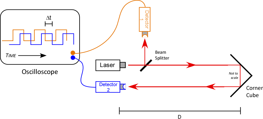
Schematic
Fall 2021 setup: Glass slide (vertical), Fresnel lens (in frame);
FreeView run in admin account (jahncke_lab)

Laser, detector 1, beam splitter, power supply,
(old) function generator, Fresnel lens in frame
Settings for Gw Instek function generator
Note that BNC cable from laser now connects to the
TTL/CMOS Output terminal on the rear of the Gw Instek function generator

Connection of new (2018) laser to power supply and
(old) function generator. Note that the BNC cable now connects to the
TTL/CMOS Output terminal on the rear of the Gw Instek function generator

Detail of new laser (2018)

Connections to power supply. Stick bare connections in plastic bag
to prevent shorting against optical table

Fresnel lens in frame, function generator, oscilloscope,
laptop, detector 2

FreeView on laptop:
v = {2(68 m) + 1 m}/460 ns = 2.98x10⁸ m/s ⇒ 0.7%!
Note that 460 ns is the sweet spot. From Fall 2021:
v = {2(68 m) + 1 m}/480 ns = 2.85x10⁸ m/s ⇒ 5%!
Trundle wheel stand
Trundle wheel at rest on stand

Assemble a 'laser shield' since laser isn't turned off between groups

Attach a piece of 3-hole punch cardboard to a pendulum clamp

The outer screws fit through 2 holes; reverse the middle screw so it doesn't get lost

The laser shield in action. Leave laser turned on between groups.

Detail of detector 1, beam splitter and laser

Detail of laser and beam splitter

Function generator settings: Square wave (formerly used Sine), 100K,
~20 on display; wire from laser is connected to TTL/CMOS BNC connector

The (old) laser connection to the function generator

Connection of laser to ±15 v power supply

Beam splitter detail

Detectors 1 & 2 connected to oscilloscope

For each connection, use a BNC T-connector, and attach a
double-banana-to-BNC adapter. Each adapter has a
10 kΩ {brown-black-orange} resistor attached.

Detector 2

Switch on detector; turn off between runs to save the battery!

Put trundle wheel under the cart

The trundle wheel

Drawers where the tinker toys for the bread board are stored

Most of the bread board stuff is in "Optical Mounts"

Box of bolts for tinker toys

Box 'o bolts

Tinker toys

You'll need an Allen key to tighten bolts on bread board

Laser focusing tool, used to tune laser appearance, if needed

Use a power strip to connect all electrical components;
a long extension cord is need to reach the nearest outlet

Professor Jahncke ponders the setup.
Note that the bread board sits on a lab cart.

The Fresnel lens, laser, beam splitter and detector

Side view

Function generator, DC power supply

Storage scope

The corner cube is placed at the other end
of the hallway, illuminated by laser

The corner cube

Illuminated by the flash!