- Computers are NOT needed for lab this week
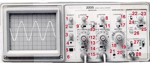
- We only have five Tektronix 2205 scopes (circa 1989 – Wikipedia), so students work in five groups.
- One of the scopes has broken knobs for intensity, horizontal and CH2 vertical position, so a small blade screwdriver is provided to make the proper adjustments.
- If anyone asks, BNC stands for "Bayonet Neill–Concelman", named after the inventors (Paul Neill, Bell Labs and Carl Concelman, Amphenol Corp.) Here's the Wikipedia page
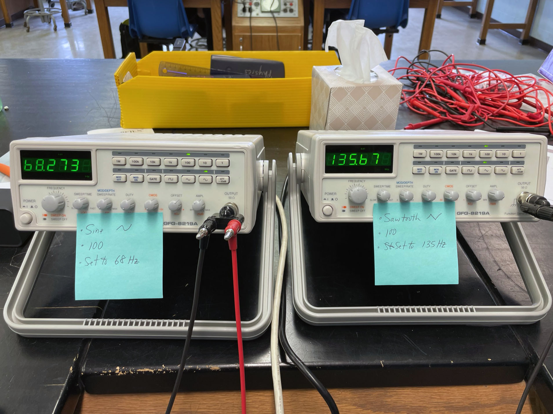
- Turn on the two function generators sitting on the instructor's bench. They provide
sine and triangle waves for students to examine
- The big power supply in the stockroom is used to distribute the function generator signals to the lab benches. Instructions: Using the Flexlab Unit to Distribute a Fixed Voltage from an External Power Supply in Lab
- The circuit diagram for connecting the function generators are found on the setup page, and photos are found on the photo details page.
- We are now using GwInstek function generators, which do not remember their settings when powered off. A sticky note should be placed on each generator so that it can be quickly configured by each lab instructor (below). The frequency knob does not need to be changed; just press the range and waveform buttons
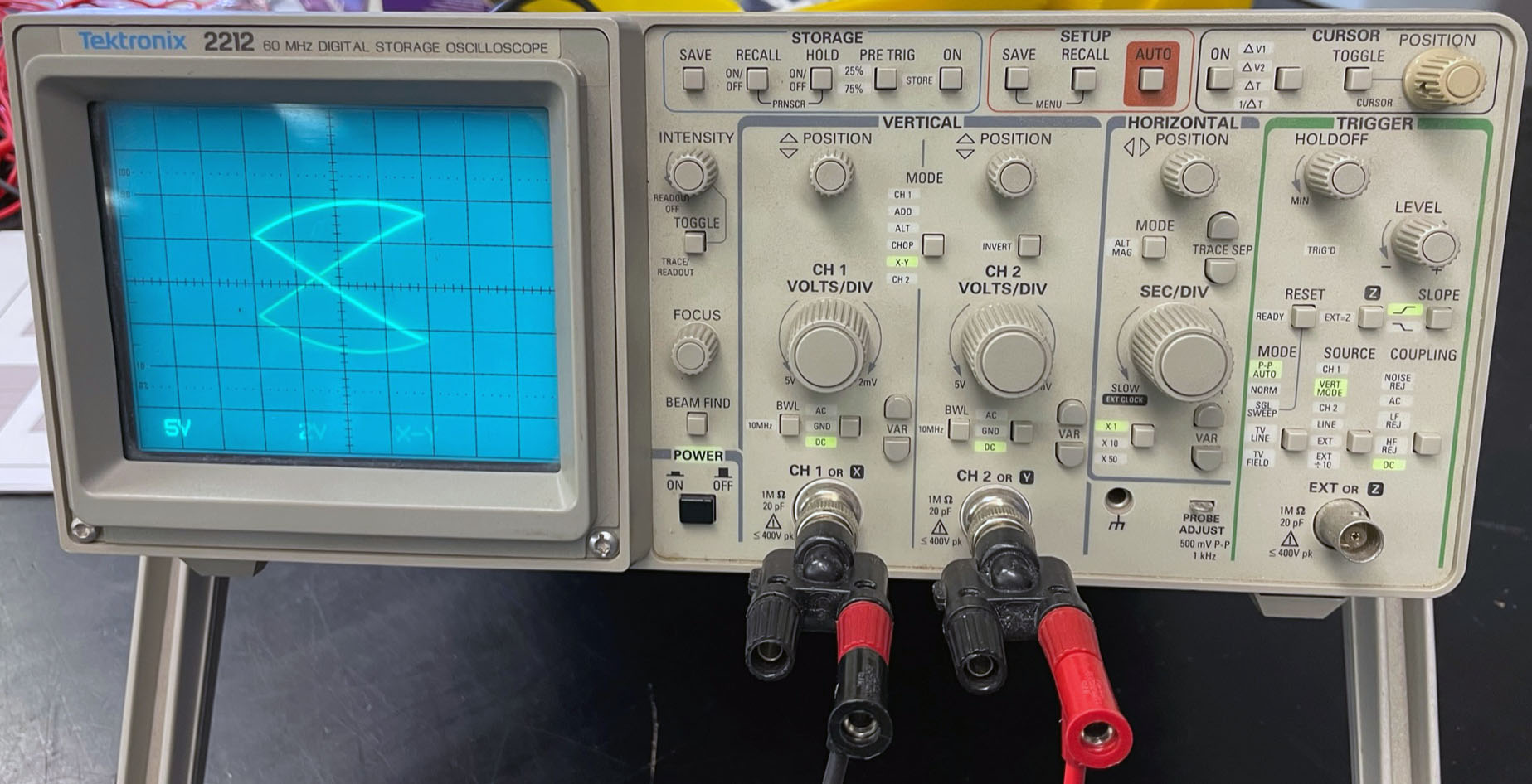
- The Tektronix 2212 oscilloscope (circa 1993 – TekWiki) on the instructor's bench is used to monitor the function generators for the sine and triangle waves. With both inputs connected and the scope set to X-Y mode, should see a nice Lissajous pattern.
- Set in X-Y mode, and the scale of both CH1 and CH2 to 2V, as shown in Figure 1 below
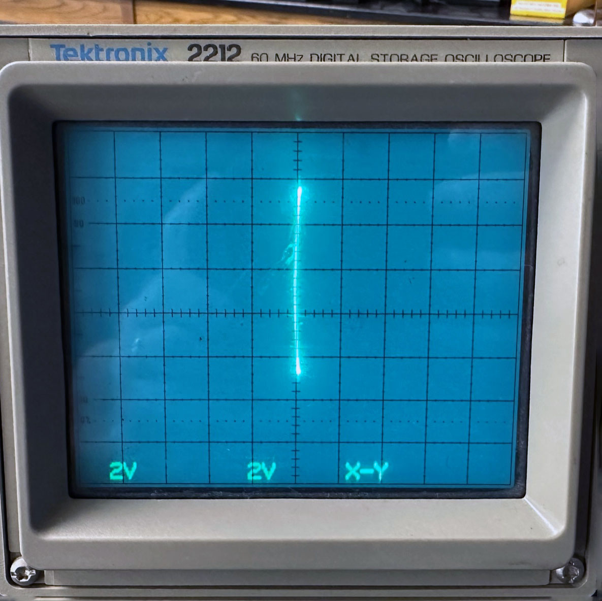
- If the pattern on this scope goes flat (Figure 2), that means that one of the students has connected their scope incorrectly and they're shorting out the signal! The incorrect connection will be on one channel: they will have the red wire connected to the green connector and the black wire connected to the red connector, or they will have the red wire connected to the red connector and the black wire connected to the black connector
 |
 |
| Figure 1: The superposition of the two signals |
Figure 2: Somebody connected their wires incorrectly |
- If the spot disappears on a student's oscilloscope, press and hold Beam Find and start twiddling with the vertical or horizontal position knobs (I find that I sometimes have to hold the Beam Find button while fiddling with the knobs!) If the wave form is not visible, adjust the vertical position knob for the channel that's connected.
- Students have a difficult time reading the setting for the voltage scale knobs (#12 in the figure from the instructions). As shown below, the voltage setting is the number closest to the left end of the bracket under "1×" (setting is circled). A cropped version of this photo now appears in the instructions, but they still have difficulties with it:

The CH1 volts/div knob is set to 1
We no longer measure the speed of sound, since it's a pain in the ass to set up each day and is essentially the same as the speed of light experiment they all performed in the fall semester. The notes are kept here for historical significance.
- Speed of sound – the instructions for this experiment depends on which scope has been set up in the hallway:
- Instructions for using the Instek GDS-1152-A-U Storage Oscilloscope:
- Turn on both microphones and amplifiers
- The scope is set to automatically trigger. Have one student loudly clap near the CH1 mic (to the right)
- Note that another loud sound will cause the scope to trigger again! When they have a good trace, press the Run/Stop button once to freeze the display. A second press of this button will clear the display
- On the scope display, the yellow signal represents CH1, the blue signal CH2 (the mic to the left)
- Press the Cursor button to reveal the cursors (pressing the button again will hide both cursors).
- Press the gray (oval) function button next to X1, and use the Variable knob to move the left cursor to the start of the yellow signal
- Press the gray function button next to X2, and use the same Variable knob to move the right cursor to the start of the blue signal
- The time delay (Δ) appears on the scope display in the box labeled X1X2. Note that the time is in milliseconds
- The computer is running FreeWave to mirror the oscilloscope screen. Click the printer button on the computer's interface to print one copy of the screen for each group. Note: Don't use the Full Screen button; you won't be able to access the printer button!
- Press the Enter key to leave full-screen mode
- Have students measure the distance between the microphone tips with the 30-m tape measure (the distance is just under 20-m)
- Instructions for using the Instek GDS-820c Storage Oscilloscope:
- Turn on both microphones and amplifiers
- The scope is set to automatically trigger. Press the “Run/Stop” button, then have one student loudly clap near the CH1 mic (to the right)
- Press the F2 button on the oscilloscope to make the vertical cursors appear, and use the Variable knob to move the
cursors. Each press of F2 will allow you to select the right or left cursor for movement. Adjust each cursor
until it is at the point where each wave starts.
- The time delay appears on the screen next to Δ
- On the computer, choose Print from the File menu, and print one copy of the screen for each group. Have them measure the distance between the microphone tips with the 30-m tape measure (the distance is about 19-m)
|