- Computers are NOT needed for lab this week
- Jeff will print copies of the conducting paper map for students to use and place on the front bench
- Here is my map with voltage measurements, equipotential lines, and three E vectors, as collected using one of our new Pasco Field Mapper Kits (Spring 2024). The new boards are much more consistent (note the position of the 0-volt line!), symmetrical, and the voltages are higher. We ask students to draw vectors with a 2:1 scale, and some vectors are very large. On my map, I decided to draw the vectors with a 1:1 scale, and they might be a bit short, so I think I'll stick with the 2:1 scale for now.
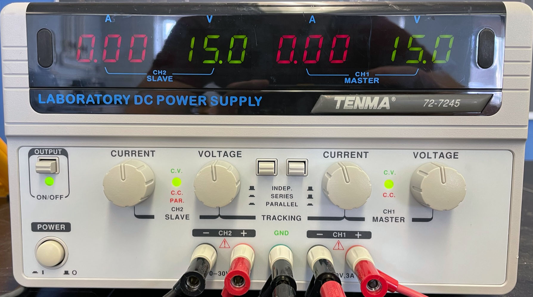
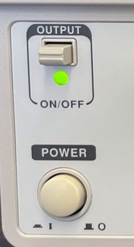 Turn on the power supply (one dual-supply, or two singles), located on front bench. Each supply is set for 15.0 volts, and wired so that they provide ±15.0 volts to the conducting sheets through the red and black connectors on the lab bench power panel Turn on the power supply (one dual-supply, or two singles), located on front bench. Each supply is set for 15.0 volts, and wired so that they provide ±15.0 volts to the conducting sheets through the red and black connectors on the lab bench power panel
- When I remember, I set all the multimeters to the hFE position, so they all start in a neutral setting and have to adjust the knobs immediately
- All of the meters will be connected from their COM port to the green power panel with a long black wire. The red meter probe is connected to the V/Ω port
- Since this is the first time they will use a multimeter, I spend a few minutes going over its basic operation as a voltmeter, and other related topics. A more thorough explanation will take place before next week's Ohm's Law lab:
- Why wires are red & black, and what's a 'banana plug'?
- The purpose of the scale settings
- Tell students to watch for a blinking 'low battery' symbol (extra meters are placed on the instructor's bench, and meters with a low battery should be replaced immediately)
- The power panel is always live; the On/Off switch controls the old timer, not the power!
- Also take a minute to discuss wire handling and safety (pull on the boot, not the wire; never leave wires dangling from a power supply)
- Students first run through an exercise where they learn to use the multimeter as a voltmeter (on the last page of the multimeter instructions)
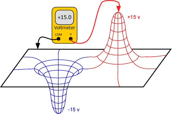
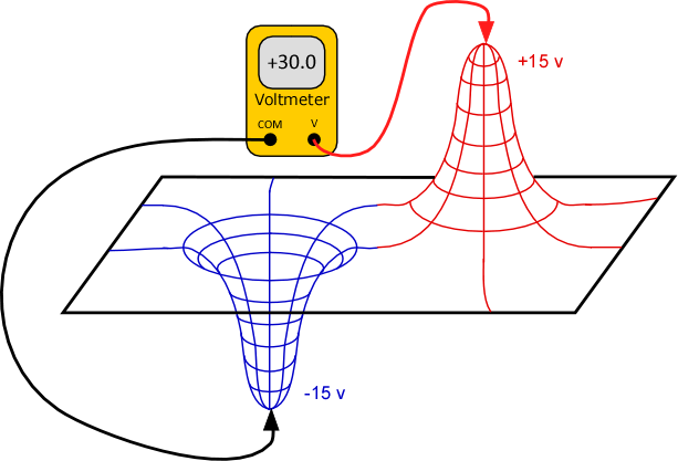
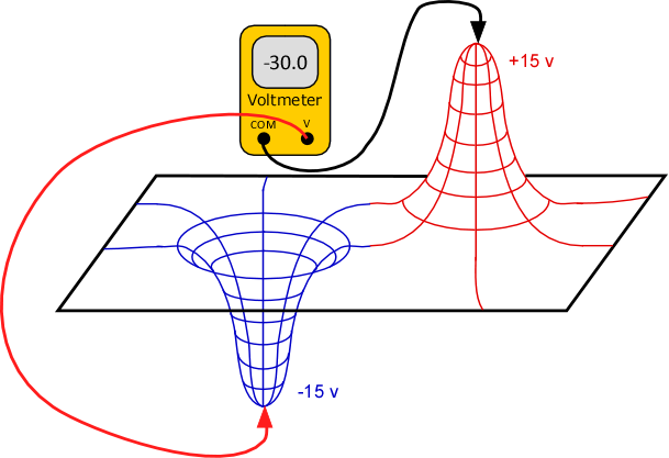
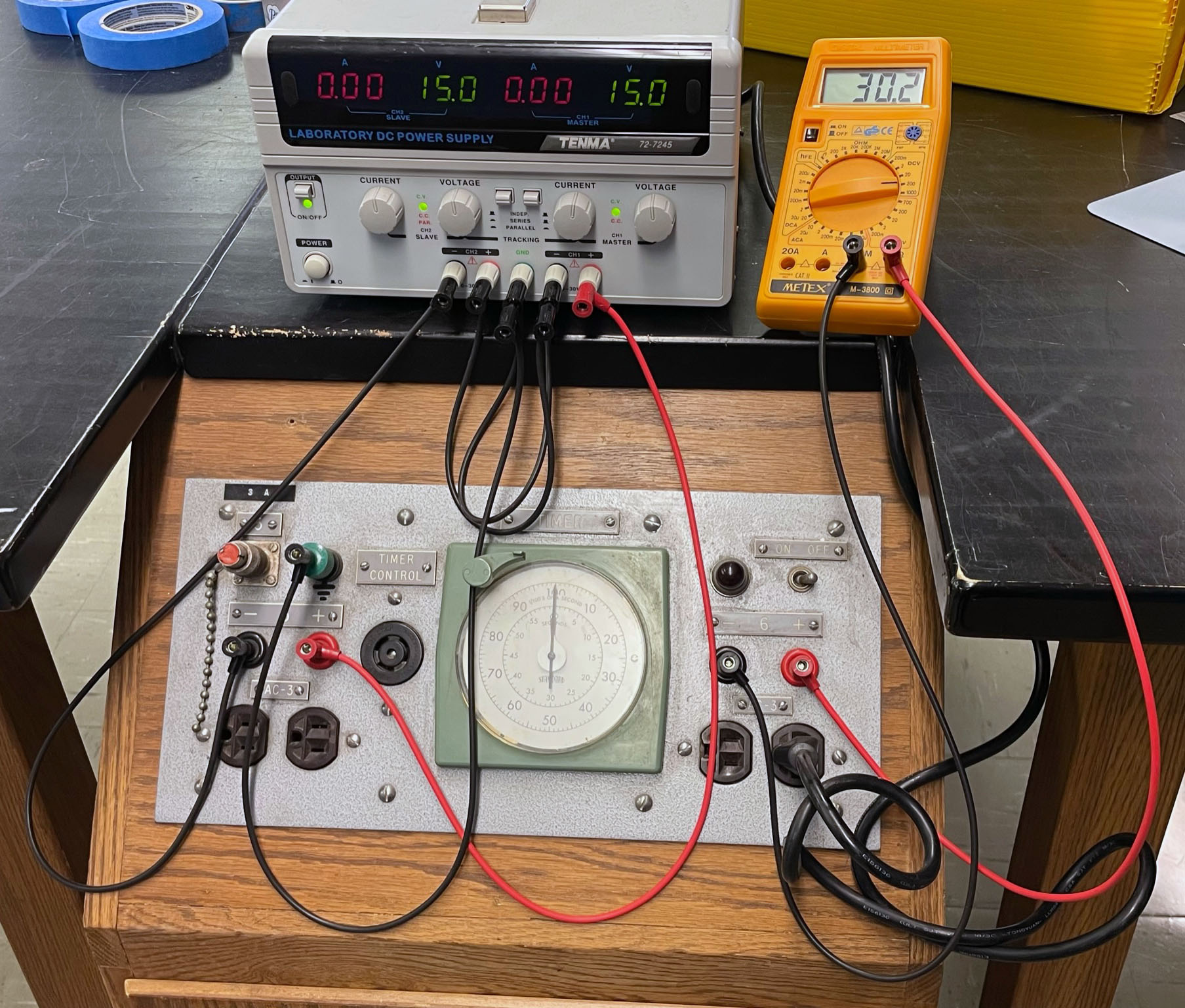
- Steps f and g of the multimeter exercise ask them about the voltage when measuring across both metal pins. Students generally expect to get 0-volts, so it's worth explaining why they get ±30-volts. You can demonstrate with their meter probes on the sketch in their directions, or with a black and red wire using the topographic map I draw on the board:
 |
 |
 |
| +15 volts, with respect to zero-potential surface |
+30 volts, with respect to the negative metal pin |
-30 volts, with respect to the positive metal pin |
- Students are provided with a copy of the 'map' along with their instructions. Each person does their own map, which they bitch about, but it's important. Frequently, one partner will draw the E vectors incorrectly, so it's an important exercise for them
- Lazy students may wish to have one write the voltages on the map, then photocopy the map. That's fine, as long as they both then plot the potential field lines and E vectors
- Student's who don't follow the directions carefully may unplug the conducting paper board from the power supply. Make sure the wire from the right-pin is plugged into the red (+15 volts) connector, the left-pin into the black (-15 volts) connector on the power panel between the benches
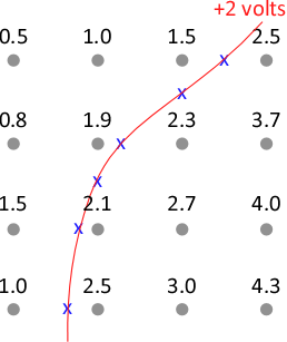 Spring 2019: Students will mark the 0-v equipotential line by dragging the meter probe along the conducting paper. Using this procedure for the other equipotential lines is tedious and produces lousy results due to the inconsistency of the conducting boards. Since we already have them measure the voltage at each marked point, they will use interpolation to determine the position of the ±2, ±4 and ±6-volt lines. I've added a picture (at right) and instructions – and didn't use the word 'interpolation' – so we'll see how that goes. Spring 2019: Students will mark the 0-v equipotential line by dragging the meter probe along the conducting paper. Using this procedure for the other equipotential lines is tedious and produces lousy results due to the inconsistency of the conducting boards. Since we already have them measure the voltage at each marked point, they will use interpolation to determine the position of the ±2, ±4 and ±6-volt lines. I've added a picture (at right) and instructions – and didn't use the word 'interpolation' – so we'll see how that goes.- Spring 2024: This is the first semester we are using the new conducting board apparatus, and they are fantastic! Most of the students were able to produce a very symmetrical potential field, and the 0-volt line goes directly up the middle! Here is a copy of the field map that I drew on the new boards
- I drew the electrodes on the conducting paper before the semester started, so that they were good and dry and at maximum conductivity when students used them. Here is the procedure I used when drawing the electrodes:
- I traced around the 3/8" circle on the green plastic template using a soft #2 pencil
- I colored in the circle using the conductive pen. I found this easier than using the conductive pen directly on the template.
- According to the Pasco product manual, the conductive ink will air dry in about 5 minutes, but it takes ~20 minutes to achieve full conductivity.
- Can I reuse the conducting paper? So far (Spring 2025), the answer is YES! I have now used them for two weeks in a row over two years and have had no issues with the boards. I'm hoping that each paper will last a very long time before needing to be replaced.
- There are a few extra, unused pages with drawn conductors in the box labeled "Board #1", in case a replacement is needed at the last moment.
- The question that still remains is how long will the conductive pens last? The manufacturer claims a shelf life of 6 months (!), and are expensive to replace (currently $81 each).
- Jeff has a spreadsheet for checking the value of the electric field components, Ex and Ey, from their voltage measurements. Be nice to him, and he'll treat you well
- Common mistakes:
- Dropping a sign when calculating Ex and Ey so that they point in the opposite direction
- Correctly calculating Ex and Ey but then graphically adding them incorrectly on the field map
- In the multimeter exploration section, thinking that the out-of-range warning is an actual measurement (they include units of volts)
- Students will write that the system "stimulates" a pair of charges. Hilarious.
|