- Computers are needed for lab this week
- Four electronic balances are needed this week (one for each bench)
- Students will study the forces between objects that interact with each other during collisions, and to examine the consequences of Newton's third law as applied to interaction forces between objects
- Remind students that the conservation of momentum means that the total momentum before collision and the total momentum after collision are the same value, in the absence of external forces, and they should always work out the algebra from the start. If they cut corners, they'll just write m1v1 = m2v2
- This lab does not require a lab journal. All students answers and calculations are written directly into the instructions. Because the instructions are lengthy, I will print copies for each lab section
- The motion detector and end stop have been flipped from last week's setup (motion detector on left side of track, end stop on right side)
- The lab bench is very busy - lots of wires and equipment used. Since there are two tracks per table, be sure that students use the computer that is connected to their track (yes, this has happened before!) I place the computer to the right of its connected track
- Make sure the force sensor cord is not making contact with the LabPro power cord. This will cause interference!
- An electronic balance is located on each lab bench
- Make sure the motion detector switch is set to Cart mode
- Remind students to put unused accessories back in the provided box when not in use (mass blocks, bolt & wing-nut, cart flag). It's easy to lose track of the small parts when they're placed on the bench
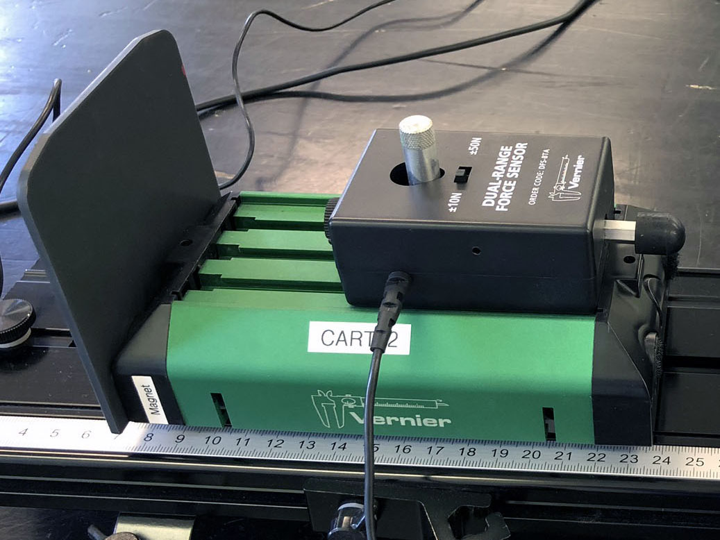
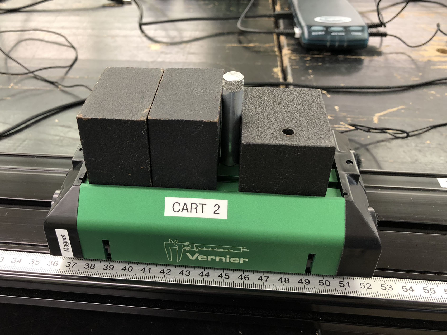 Students should leave the mounting post on each cart when doing the first simulation (a qualitative examination of the collision of two carts of differing mass), as shown at right. The post is used to attach the force sensor (used later), and should be located in the correct position. The bolt & wing-nut are not needed to attach the cart masses Students should leave the mounting post on each cart when doing the first simulation (a qualitative examination of the collision of two carts of differing mass), as shown at right. The post is used to attach the force sensor (used later), and should be located in the correct position. The bolt & wing-nut are not needed to attach the cart masses- When attaching the force sensors to the carts, it's important that the sensors are attached so that they lay flat on the surface of the cart (the front edge of the sensor shouldn't be on the 'lip' around the top), and but the front of the sensor housing must be butted up against this lip so that the sensor doesn't move right or left during collisions. The mounting post should be in the correct position near one side of the cart, but it tends to slip and can be a pain to attach the force sensor in the correct position. Here's how I do it:
- Unscrew the post a little so that it can move
- Set the force sensor on top of the post, but loosely tighten the force sensor screw so that the post can still rotate
- While holding the force sensor body tightly against the lip of the cart, tighten the mounting post while pushing it against the front of the force sensor body
- If the mounting post is in the correct position, you should be able to tighten the force sensor screw and have it firmly attached to the post.
- If the mounting post is not in the correct position, the sensor will move away from the lip of the cart when the force sensor screw is tightened. If this happens, loosen the force sensor screw and mounting post, and try again
- When students are performing the first calculation (page 1), I tell them to write out the algebra and keep track of their signs. And if they wrote "m1v1 = m2v2", they're doing it wrong!
- When performing the simulation on page 4 of the instructions (equal forces), be sure that the sensor connected to CH1 is on the left cart, CH2 on the right. Students will get unexpected results if they switch the sensors
- The measured force should be the same value on each sensor. Any difference is most likely due to the different calibrations of the force sensors; the difference is typically around 2%, but can be as high as 5%. This can be checked by noting that measured force from the sensor on one cart is always higher than from the other sensor
- The final activity requires that one mass block is attached to the back of Cart A. The bolt & wing-nut must be used in this case to keep the mass from sliding around during the cart's collision with Cart B. A sketch in the instructions clearly shows how this mass is attached, but many still don't get it right since many have never used a wing-nut before *sigh*
-
 The final activity also requires that a cart flag is attached to the back of Cart A; this gives the motion detector a good flat surface, and produces a very clean trace on the graph showing the velocity of time. The magnetic cart flags work well, as shown at right The final activity also requires that a cart flag is attached to the back of Cart A; this gives the motion detector a good flat surface, and produces a very clean trace on the graph showing the velocity of time. The magnetic cart flags work well, as shown at right
|